manifold

When was the last time a “12-week lead time” helped your project stay on schedule.

The Hidden Cost of Custom Everything

There’s a trend in hydraulics toward custom solutions for every application. Custom manifolds. Custom valve assemblies. Custom pressure settings. It sounds sophisticated until you face real-world consequences:

  • Production schedules built around hoped-for delivery dates
  • Emergency repairs waiting on special-order components
  • Inventory nightmares from supporting dozens of unique part numbers
  • Engineering time spent specifying variations that add complexity without performance benefit

Sometimes the smartest solution is the one that’s actually available.

When Standard Means Better

Bosch Rexroth’s DBD 6-30 pressure relief valves prove that standardized doesn’t mean compromised. These direct-operated relief valves combine proven performance with the practical advantage of consistent stock availability.

Four sizes. 50 to 330 l/min flow capacity covers most mobile and industrial requirements.

Seven pressure ratings. From 25 to 630 bar—low-pressure mobile equipment through high-force industrial presses.

Multiple configurations. Cartridge, threaded, or subplate mounting. Tool-adjustable or hand-adjustable. Standard or enhanced corrosion protection.

The combinations you actually need? Ready to ship.
One Valve. Both Strengths.

Reliability Through Simplicity

DBD valves use direct-operated design where system pressure acts directly against a calibrated spring. When pressure exceeds the setting, the valve opens proportionally.

No pilot stages creating delays. No complex controls introducing failure points. Just mechanical reliability that works the same way every cycle.

This simplicity delivers real advantages:

  • Predictable response when pressure approaches limits—no pilot delays, just direct mechanical action.
  • Straightforward service when maintenance is needed—springs and seals, not multi-stage troubleshooting.
  • Consistent performance across temperature ranges and fluid conditions because mechanical operation doesn’t depend on pilot signal quality.

Built for Tough Conditions

Pressure relief valves often end up in exposed locations where environment challenges longevity. That’s why DBD valves offer corrosion protection levels matched to actual conditions:

  • Standard protection handles typical indoor industrial environments.
  • J3 protection (240-hour salt spray resistance) suits outdoor installations, mobile equipment, or humid conditions where condensation occurs regularly.
  • J5 protection (720-hour salt spray resistance) addresses marine applications, coastal facilities, or chemical processing where standard coatings fail within months.
  • The protection isn’t cosmetic—it’s functional reliability. Corrosion affects spring characteristics and sealing surfaces. Protected valves maintain calibration where unprotected alternatives degrade.

High Pressure Without Hesitation

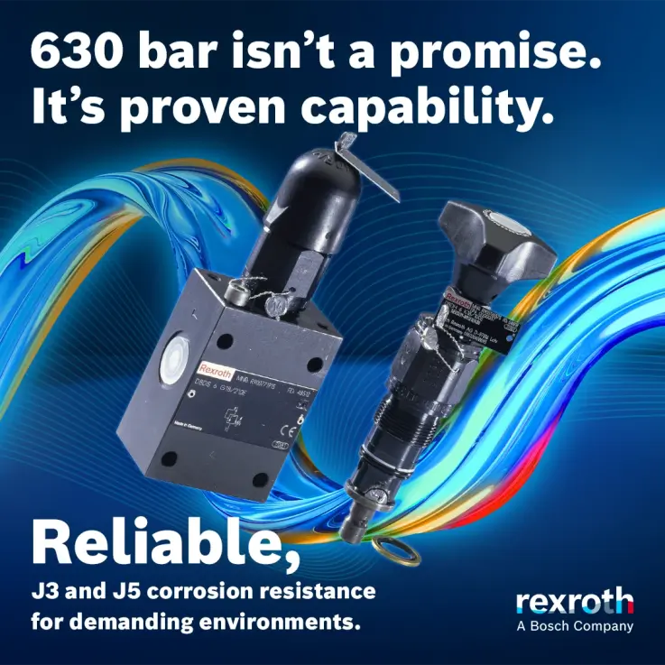
Maximum ratings of 630 bar aren’t theoretical—they’re proven operating capability. Steel construction, hardened sealing surfaces, and precision manufacturing ensure DBD valves maintain performance and reliability when actually operating at high pressures.

For systems running 315 bar, 400 bar, or 630 bar, you’re not pushing design limits. You’re working within validated capability backed by decades of field installations.

The Availability Equation

Here’s what changes when critical components are consistently available:

  • Design confidence – Build schedules around actual delivery, not hoped-for dates.
  • Simplified inventory – Stock one reliable valve family instead of maintaining emergency supplies of multiple alternatives.
  • Faster emergency response – When pressure protection fails, replacement arrives in days.
  • Reduced planning stress – “Is it available?” stops being a question you ask weekly.

Quality That Shows Up Consistently

Rexroth manufacturing standards ensure every DBD valve meets specifications:

  • Precision machining of sealing surfaces
  • Controlled spring calibration with verification
  • Functional pressure testing before shipment
  • Consistent performance across every unit with the same part number

When you install a DBD valve, it performs like every other valve with that specification—predictable, repeatable, reliable.

When Simple Wins

Sophisticated solutions have their place. But when you need reliable pressure protection that’s available when projects demand it, proven when systems depend on it, and consistent when production requires it—standardized excellence beats custom complexity.

DBD 6-30 pressure relief valves: the smart choice that’s actually in stock.

Want to see how standardized reliability can simplify your next project? Contact Bosch Rexroth to discuss your pressure protection requirements.

CMA/Flodyne/Hydradyne is an authorized Bosch Rexroth distributor in Illinois, Wisconsin, Iowa and Northern Indiana.

In addition to distribution, we design and fabricate complete engineered systems, including hydraulic power units, electrical control panels, pneumatic panels & aluminum framing. Our advanced components and system solutions are found in a wide variety of industrial applications such as wind energy, solar energy, process control and more.
Best Practices: Inconsequential Volume

Guest Contributor: SMC

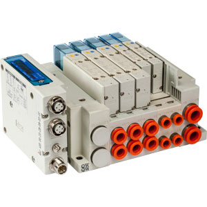
The advent of manifold mounted, plug-in pneumatic valves has been a boon for machine builders. It allows them to mount complete valve packages in a safe and secure location on a machine. Using a D-sub connector, serial interface module, or similar single-point wiring system, all of the electrical control outputs can feed into one location on the manifold, greatly simplifying the wiring. Plumbing issues are reduced, since a single air pressure line can be used to feed a common pressure gallery. The same advantage applies to the common exhaust gallery. No longer would both a plumber and an electrician be required to replace a valve, since any valve can be replaced without disturbing electrical connections or plumbing lines.ex260_ported

Like most advances, there can be some downsides to this type of arrangement, depending upon the application. One of these revolves around considerations for energy conservation. Most circuits include two air lines extending from the valve to the actuator, one for extend and one for retract. Each time the valve cycles, the actuator is pressurized on one side or the other. Of course, the hose or tube that connects them must also be pressurized. This tubing volume is typically ignored as inconsequential when doing our sizing calculations, but should not always be overlooked.

The tubing volume offers no work at all…only a means of transferring the energy of the compressed air to the actuator. Inconsequential? Maybe. But depending upon the application, those volumes can be significant. Here is an example:

A packaging facility has corrugated boxes being erected at a mezzanine level and dropped down to the main floor where they are filled, sealed and palletized. The box drop-down employs gravity to lower the boxes, but incorporates a series of mechanical stops to sequence them as required. Each of the stops includes a pair of 2 inch bore x 1 inch stroke air cylinders to operate a brake that stops the box and releases it when needed. In all, four stops are included for each drop down, meaning eight actuators in total and four valves to control them.

The directional control valves are located at a central location on a single manifold, presenting a clean and compact package. However, the distance from manifold to actuator varies from 10  feet to 25 feet. In operation, each time a valve shifts, it exhausts one length of tubing and fills another. Given the small volume, we might still think this to be inconsequential, but let’s look at the numbers.

Assume ¼” OD tubing with an ID of approximately .180“. With the first station being 10 feet away from the valve, the volume of tubing going to the actuators is only 3.05 cubic inches. Since there are two lines from the valve to each actuator pair, the total volume is 6.10 cubic inches per complete cycle. To put this in perspective, each of the 2×1” cylinders has a total volume of 5-½ cubic inches. That’s the sum of both the extend and retract sides. Since there are two of them, the total cylinder volume is 11 cubic inches. The volume in the tubing is over half that of the actuators. Much of the energy developed at the compressor is being used to fill the tubing lines.

Let’s leave aside the potential problem with poor response times, and just look at the costs. Let’s also assume the working pressure to be 80 psi. By calculating the compression ratio to be 6.33, and multiplying that by the volume, the normalized volume becomes 38.6 standard cubic inches. If we have the cylinders being actuated five times a minute, we will be consuming 193 standard cubic inches per minute, or using more meaningful terms, 0.11 SCFM. That is just for filling the air tubing to the closest single station on the drop-down. How about the other 3 stops on the drop-down?

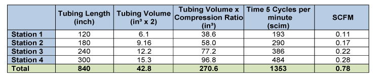
The chart below shows the air volume for each of the stations, with a total for all. Please note the total volume of the airlines extending out to the cylinders is 42.8 in³. When we calculate the total volume of all eight cylinders we get 44 in³. The volumes are almost identical. Now we have a situation where half the compressed air is consumed filling all the air lines.

smc-iv

If that single drop down operates 24/7 and the cost for electricity is $.10 per KWh, the annual cost to fill those lines is about $110, the same costs we incur to fill the cylinders. With multiple drop-downs, the costs are multiplied. Staying with our example, the facility has 50 packaging lines, for an annual cost of $5500.

While this may be viewed as an extreme example, think back on all the applications where long air feed lines were employed in order to have a clean valve package. Or consider the oversize tubing that was utilized just because it was handy. Many of us might figure that larger tubing is better anyway, and everything will run more efficiently. However, please take into account that the larger tubing may double the volume to be filled without adding any productive benefit at all.

What happens to the same example when 3/8 inch tubing is used instead of the ¼ inch? The tubing ID increases to .27 inches and the volumes increase by a factor of 2.28, as do the costs. Now the annual price tag has jumped to $250. Again…that is just to fill the tubing for one drop-down.

As a side note, there is also some potential for liquid moisture build-up in those long lines when an excess of air is left between the valve and the actuator, even when good air filtration and drying is in place. Problems can arise due to the adiabatic expansion that occurs with each exhaust cycle. Condensation may occur as the exhausting air temperature falls below that of the atmospheric dew point. With long air lines and many cycles, the moisture may not be completely exhausted and can accumulate in the lines. That accumulation will occur near the actuator ports and will eventually work its way into the actuator, shortening its life.

What’s the solution? Have the valves mounted on or near the actuators so that all or most of the air volume is used to actuate the cylinders. This will require a pressure line running the length of the drop-down with a connection to each valve. However, that pressure line represents energy capacitance that works in our favor. We will also have fewer connections, which will translate into fewer potential leaks. Of course, the downside is that electrical lines will have to be extended independently to each valve. However, with low voltage, low wattage coils, this probably is not that difficult. Another benefit to be gained is that electrical response times remain unaffected, while pneumatic response times improve dramatically.  The dollar savings is the reduction in air consumption by half. In our plant, that could be up to $5500.00 every year.

Reducing the costs for compressed air needs to be an ongoing project for any company that uses substantial amounts of air as part of the manufacturing process. There is a tendency to approach the issue at the compressor room and look for answers there. The resulting recommendations can be expensive as well as require a long ROI. However, dealing with demand side issues, as described here, offers an easy solution that can be incorporated at the OEM level with little additional cost. A case can even be made for modifying these types of applications in the field when machines come due for refurbishment. Addressing these “inconsequential” issues will offer significant savings on the bottom line. “Watch the pennies and the dollars take care of themselves”.

To learn more about Best Practices in Pneumatics, please visit http://www.smcusa.com/

About Us

cropped-cmafh-logo-with-tagline-caps.png

CMA/Flodyne/Hydradyne is an authorized  SMC distributor in Illinois, Wisconsin, Iowa and Northern Indiana.

In addition to distribution, we design and fabricate complete engineered systems, including hydraulic power units, electrical control panels, pneumatic panels & aluminum framing. Our advanced components and system solutions are found in a wide variety of industrial applications such as wind energy, solar energy, process control and more.