Bosch Rexroth Web Editorial TeamEditor
When every square inch of factory floor space costs money, why are machine tools still using bulky hydraulic power units that waste half their footprint?
The Installation Space Problem
Machine tool manufacturers face a constant challenge: customers want more capability in less space. As workpieces get smaller and precision requirements increase, every component needs to justify the room it occupies.
Traditional hydraulic power units haven’t kept pace with this miniaturization trend. A standard 4 kW unit typically requires 100 liters of oil capacity, a separate control cabinet, external cooling circuits, and enough clearance for maintenance access. That’s a lot of real estate for what’s essentially a support system.
Four Innovations That Changed Everything
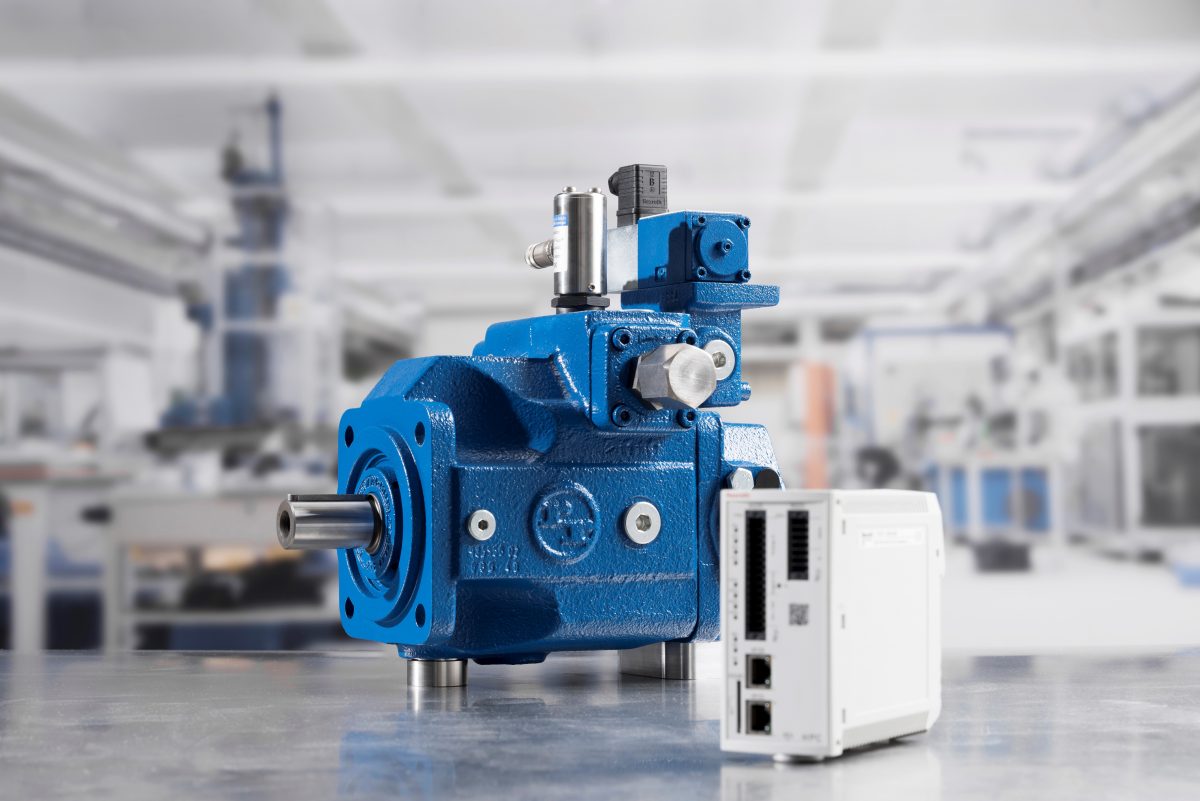
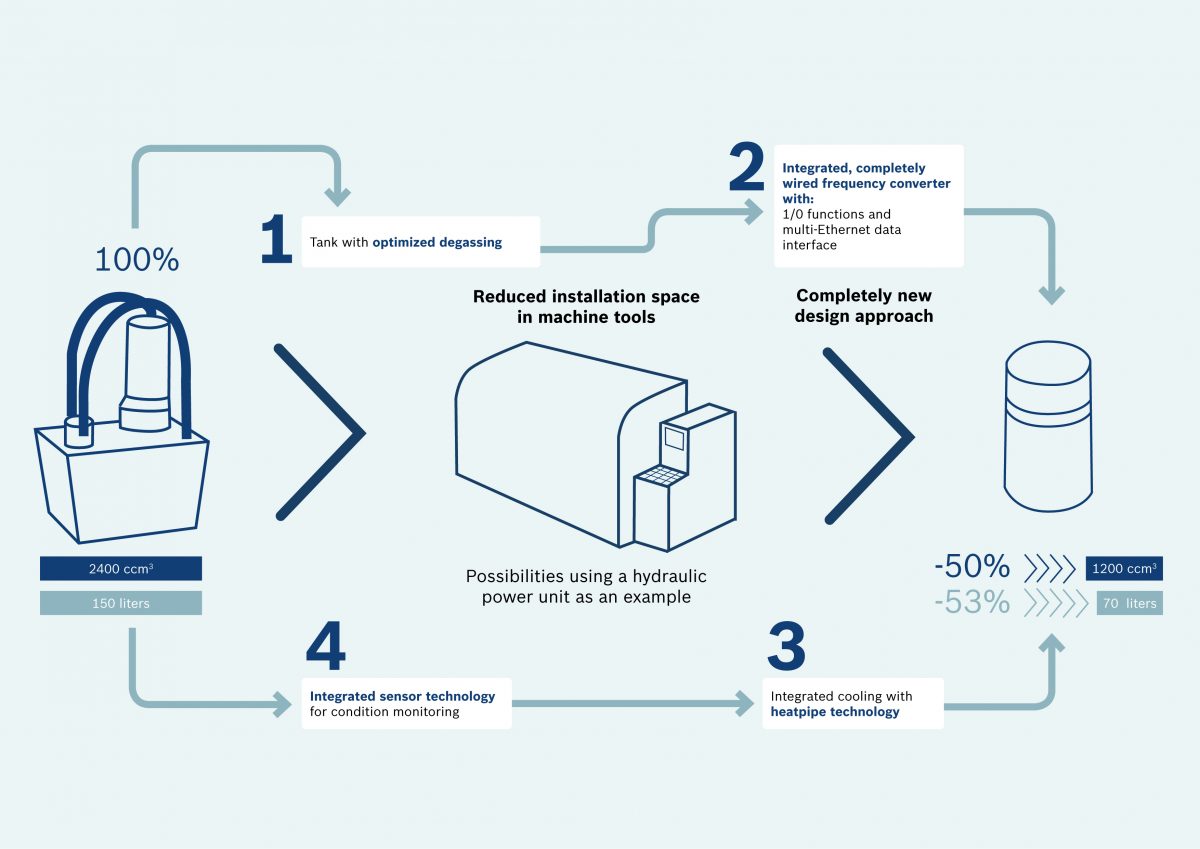
Bosch Rexroth’s CytroPac takes a completely different approach—one that eliminates the traditional “installation space eaters” through intelligent integration:
1. Optimized Tank Design
By rethinking how oil degasses, engineers reduced tank volume by 80%—from 100 liters down to just 20 liters. That’s the same hydraulic performance in half the space.
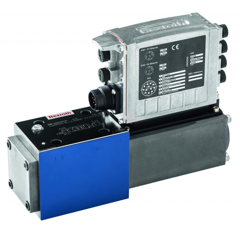
2. Integrated Frequency Converter
The fully-wired frequency converter with multi-Ethernet interface lives inside the power unit itself. No separate control cabinet required. For many installations, that eliminates cabinet space entirely.
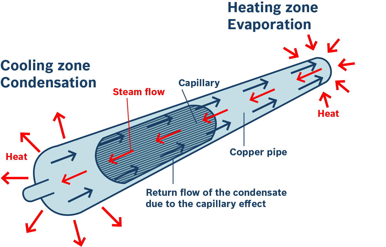
3. Heatpipe Cooling Technology
Instead of bulky cooling circuits, passive heatpipes transfer thermal energy from the motor, converter, and oil to a central cooling water connection. This cuts another layer of complexity and space consumption.
4. Built-in Condition Monitoring
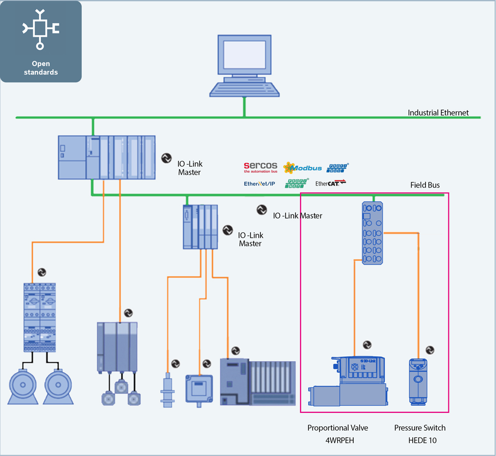
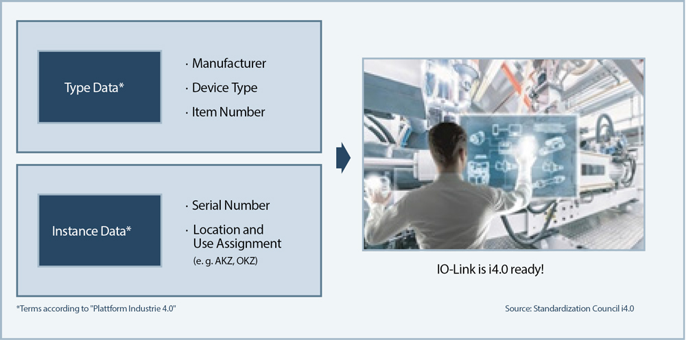
Integrated sensors monitor fill level, temperature, pressure, and filter contamination—feeding data directly to Industry 4.0 systems through standard interfaces like Ethernet-IP, EtherCAT, and Profinet.
The Quiet Revolution: Noise Reduction Benefits
Manufacturing environments face increasing pressure to reduce workplace noise levels—both for operator comfort and regulatory compliance. Traditional hydraulic power units contribute significantly to ambient noise through pump operation, cooling fans, and pressure fluctuations during load changes.
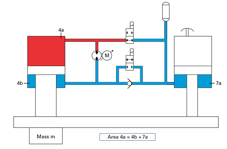
CytroPac addresses this through multiple integrated design features. The variable-speed drive eliminates the constant high-RPM operation that characterizes fixed-speed systems—the pump only runs as fast as needed for current demand. Combined with optimized tank design that reduces fluid turbulence and heatpipe cooling that eliminates noisy cooling fans, overall sound emissions drop noticeably. Machine tool builders report quieter operation that improves the working environment without requiring additional sound insulation or enclosures.
Energy Efficiency That Pays Back
Energy costs represent a growing portion of manufacturing overhead, making hydraulic system efficiency more than an environmental consideration—it’s an economic one. Traditional fixed-speed hydraulic systems run at full capacity regardless of actual demand, wasting energy during idle periods and low-load operations.
CytroPac’s integrated frequency converter fundamentally changes this equation. The variable-speed drive adjusts pump speed continuously to match hydraulic demand, consuming energy proportional to actual work performed. This approach complies with EU Eco-Design Directive 2009/125/EC while delivering measurable cost savings. In typical machine tool duty cycles with significant idle time between operations, energy consumption can drop 30-50% compared to conventional fixed-speed units. For manufacturers running multiple machines across shifts, those savings compound quickly—turning energy efficiency from a compliance requirement into a competitive advantage.

What This Means in Practice
The total footprint reduction? Up to 50% compared to conventional designs of equivalent performance.
But space savings aren’t the only benefit. Machine builders also gain:
- Faster installation: Connect power, cooling water, data interface, and hydraulic supply—done
- Reduced assembly errors: Everything’s pre-wired and tested at the factory
- Lower total cost: Smaller footprint means smaller machine frame or larger work envelope
- Future-ready connectivity: Condition monitoring enables predictive maintenance strategies
The Control Cabinet Question
Here’s where integration really pays off. When the frequency converter, sensor technology, and motor are all pre-wired within the power unit, many machine designs can eliminate the hydraulic control cabinet completely.
Even when cabinet space remains necessary for other systems, reducing its footprint by 100% for the hydraulic portion creates flexibility for other components or simply reduces the overall machine size.
A Different Design Philosophy
CytroPac represents a fundamental rethinking of what a hydraulic power unit should be. Rather than optimizing individual components and assembling them, the approach integrates everything from the start—designing for the complete system performance in minimum space.
This matters because machine tool economics increasingly favor compact, flexible designs. When manufacturers can offer the same machining capability in a smaller footprint, they win business. When they can integrate hydraulics without sacrificing valuable working space, they differentiate their products.
Beyond Just Smaller
Miniaturization alone wouldn’t justify redesigning a proven technology. But when you combine space savings with energy efficiency (variable-speed drives only consume what’s needed), simplified installation (plug-and-play connectivity), and Industry 4.0 readiness (integrated condition monitoring), the value proposition becomes compelling.
Machine tool builders working in the 4 kW performance range now have an alternative to the “bigger tank, bigger cabinet, bigger footprint” tradition.
Want to see how much space CytroPac could save in your next machine design? Bosch Rexroth application engineers can evaluate your specific requirements and demonstrate the integration advantages.
CMA/Flodyne/Hydradyne is an authorized Bosch Rexroth distributor in Illinois, Wisconsin, Iowa and Northern Indiana.
In addition to distribution, we design and fabricate complete engineered systems, including hydraulic power units, electrical control panels, pneumatic panels & aluminum framing. Our advanced components and system solutions are found in a wide variety of industrial applications such as wind energy, solar energy, process control and more.

 No drive technology is more efficient, compact and robust than hydraulics when dealing with forces in excess of 600 kN. So why is it that the importance of hydraulics is often overlooked in the training and development of our young engineers?


 Regarding the Sytronix family, Rexroth offers more than one hundred pump drives with variable speed relating to power and function. These can be integrated into all usual automation structures thanks to multi-Ethernet interfaces.