Hydraulic Cylinders

PERFORMANT AS ON DAY ONE: WHY HYDRAULICS MUST BE REPAIRED THE ORIGINAL WAY

Guest Contributor, Bosch Rexroth

Hydraulic drives move high loads and ensure safety-relevant functions. Their failure can result in tremendous downtime costs. It is therefore important to maintain the interaction between material, surface quality and fluid as coordinated by the manufacturer. With spare parts and repairs according to original specifications, operators can secure original performance over a long period of time.

Every year, millions of euros are invested in the development of new hydraulic components. Each new generation of solutions is even more powerful, energy efficient and reliable than the one before. The underlying field of research is called tribology – the science of friction, lubrication and wear.

Ensuring smooth performance

Tribology investigates all frictional processes that occur between two surfaces moving in relation to each other and considers the type of material, surface quality and the lubricant (fluid) as the main influencing variables. If hydraulic components are developed according to tribological principles, important savings can be made both in energy and material consumption and in production and maintenance. How can operators secure the advantages of the latest product generation for as long as possible?

Figure1.png

Figure 1: Material, surface and lubrication: The scientific field of tribology investigates the friction between two bodies and seeks optimal conditions for minimal wear.

Change a perfect system? Better not!

Hydraulic components in which materials, surfaces and fluid are matched to each other in such a way that they achieve optimum efficiency with minimum wear are called a “tribological system”. This perfect interaction stands and falls with maintenance. If only a single parameter is changed, the system loses its balance, i.e. the optimum efficiency is no longer achieved, energy consumption and electricity costs increase and the service life is negatively affected. This happens, for example, if spare parts made of a different material or with a lower surface quality are used, if components are improperly repaired or a fluid is used that does not match the material.

Figure2.png

Figure 2: Fluid-related damage to various components of an axial piston pump.

Play it safe: Spare parts from the manufacturer

To prevent operators from suffering functional losses and damage, Bosch Rexroth subjects the evaluation of fluids to strict requirements that go far beyond the recommended standard. The manufacturer also sets the same high-quality standards for its own spare part production as for the original. Replicas, on the other hand, offer neither the same material composition nor the same surface quality. The consequences are unplanned outages, significantly higher life cycle costs and premature new investments. Choosing original spare part is already worthwhile with the smallest parts. For example, Bosch Rexroth provides completely ready-to-install seal kits in original equipment quality – including parts list and exploded drawing. Thanks to the precise instructions, the average time required for dismantling, cleaning and reassembling a pump is reduced from a good two hours to less than 60 minutes.

Figure3.png

Figure 3: Surface comparison: In contrast to the original from Bosch Rexroth (left), the plagiarism (right) shows large scores. The unfavorable flow conditions decrease efficiency. Leakage and cavitation are increased, especially under high pressure.

Abb4.png

Figure 4: Serious quality differences in material and processing: The plagiarism (right) cannot withstand high pressure and “breaks”. The result: premature wear and tear and damage due to liquid contamination.

Original repair receives manufacturer specification

Repairs that are not commissioned at the manufacturer or certified partners often also result in unforeseen expenses. This is because without access to current data and parts lists, without in-depth know-how and without the right test benches, other suppliers cannot restore the original specification including functional reliability. In the worst case, there is even a risk of liability.

What ultimately distinguishes an original repair from an uncertified one? Here’s an example: When a Bosch Rexroth axial piston pump is inspected and repaired by trained service personnel in a specially equipped, ISO 9001-certified service center, it undergoes qualified testing and repair according to standard guidelines and processes. All failure-critical components are replaced and the original manufacturer’s specification is tested and confirmed on the test bench.

Replacement is better than rework

Non-certified suppliers frequently rework components, thereby destroying the original surface quality of highly stressed components such as pistons with slide shoe, control plates or sliding disks. Control valves on pumps are usually only cleaned and reinstalled. This short-sighted repair practice leads to increased leakage and consequently to a strong vibration tendency. Both accelerate wear, reduce efficiency and shorten the service life. By repairing with original Rexroth spare parts from the manufacturer, however, operators can ensure the original performance and availability for the next few years, including a twelve-month warranty on new parts. In addition, fixed-price repairs and agreed throughput times ensure cost security. This way, operators are protected from surprises and can plan ahead.

Figure5.png

Figure 5: Rework vs. replacement: Leakage oil measurements on a remanufactured pump controller (A4VSO) show significantly higher values than when the original component is replaced: Vibrations, increased wear and early failures can be the result.

Avoiding liability risks

In some countries, improper repairs can also result in liability risks for the operator. In Germany, for example, the manufacturer is not liable under § 1 Sections 2 and 3 ProdHaftG (German Product Liability Act ) for defects that occur after the product has been placed on the market. Instead, the operator is responsible for the consequences of improper repairs. If the operational safety according to the CE mark is no longer given, the insurance company might not pay for damages.

Our conclusion: Sometimes saving money doesn’t pay off – preserve values instead

Those who want to save costs in the short term – by using counterfeit products and non-original repairs – pay extra in the long term. To benefit permanently from the original performance and a long service life, it pays off to include the manufacturer’s expertise in terms of technology, industry and application in maintenance, too. Only with proven manufacturer specifications can the original performance data and resulting function, productivity and efficiency be guaranteed.

Close cooperation with Bosch Rexroth is also worthwhile for other reasons: for example for engineering support, for professional instruction and training of operating and maintenance personnel, or to update the cost-effectiveness, energy efficiency and safety of existing systems. This way, a supplier relationship becomes a profitable partnership for a perfectly smooth operation.

CMA/Flodyne/Hydradyne is an authorized Bosch Rexroth distributor in Illinois, Wisconsin, Iowa and Northern Indiana.

In addition to distribution, we design and fabricate complete engineered systems, including hydraulic power units, electrical control panels, pneumatic panels & aluminum framing. Our advanced components and system solutions are found in a wide variety of industrial applications such as wind energy, solar energy, process control and more.

________________________________________________________________________________________________________________________

5 HYDRAULICS MYTHS

Guest Contributor: Dr. Steffen Haack, Bosch Rexroth

br_hydrolicmyths_hero_dec19.jpgNo drive technology is more efficient, compact and robust than hydraulics when dealing with forces in excess of 600 kN. So why is it that the importance of hydraulics is often overlooked in the training and development of our young engineers?

In the modern manufacturing setting, movement is everything along with the resulting data. Little thought is given to hydraulic technology, that is until drive physics comes into play. This is when hydraulic technology comes into its own in managing large forces and delivering robust performance.

Here’s a connected hydraulics ‘Myth Buster’ that demonstrates how the latest smart hydraulics are more versatile and cost-effective than you ever imagined.

THE MYTH: Installation is complex

BUSTED: Designers are no longer required to develop an in-depth knowledge of fluid mechanics and technology and increasingly look for plug & produce modules. These ready-to-install modules simply need an electrical current and a connection to the control communication.

THE MYTH: Commissioning takes time

BUSTED: Our smart, connected hydraulics are now commissioned with the same engineering tools as electric drives and control systems. Functions previously carried out hydromechanically are handled by the latest drive software. There are even software assistants available to guide technicians through the commissioning process and suggest suitable parameters.

THE MYTH: Hydraulics waste energy

BUSTED: There’s a preconception that hydraulics are more energy-intensive than other technologies, but things have changed dramatically. Variable-speed pump drives generate the flow in line with demand and reduce speeds accordingly under partial load conditions. Compared to constantly driven pumps, they reduce power consumption by up to 80 percent – a level consistent with that of electric drives of the same size.

THE MYTH: Hydraulics aren’t IoT ready

BUSTED: Smart hydraulics are a well-established part of IoT in production. Analog valves can be made digitally visible cost-effectively thanks to IO-Link and exchange data available through the control system. Smart valves, with their own control electronics and state of the art field bus connection, are as convenient to use as electric drives.

THE MYTH: Hydraulics are high maintenance

BUSTED: Hydraulics offer a distinct advantage when monitoring operating states and deducing possible wear and expected life cycle. With a few pieces of sensor data, such as pressure differential, oil temperature, optically measured contamination or pressure increase over time, software can assess the health of the system.

This myth busting technology is included in our latest generation of hydraulic power units, allowing young designers and businesses to benefit from all the advantages of our modern, connected innovations.


CMA/Flodyne/Hydradyne is an authorized Bosch Rexroth distributor in Illinois, Wisconsin, Iowa and Northern Indiana.

In addition to distribution, we design and fabricate complete engineered systems, including hydraulic power units, electrical control panels, pneumatic panels & aluminum framing. Our advanced components and system solutions are found in a wide variety of industrial applications such as wind energy, solar energy, process control and more.

Hydraulic Valves – Customize your Feedback

Guest contributor: Chris Heberlein, Balluff

Hydraulic actuators can be used to open and close a valve’s position.  In automation architectures, a linear position sensor is used within the hydraulic actuator to provide continuous position feedback.

The linear position sensor is installed into the back end of the cylinder.  The sensing element resides in a cavity that has been gun-drilled through the piston and cylinder rod, Image1extending the full length of the mechanical stroke. A magnet ring is used as a position marker and mounted on the face of the piston.  As the piston (and the position marker) move, the linear position sensor provides a continuous absolute position by way of an analog or digital signal.

In some applications, a cylinder’s position may only be moving across a small portion of the overall stroke or a specific portion of the stroke.  The end user could benefit from altering the transducer’s signal based on the application’s specific stroke requirements instead of the entire cylinder’s stroke, thereby maximizing available position resolution.  When this situation arises, most transducer manufacturers offer the ability to customize or “teach” a modified output of the stroke via push buttons or from wiring inputs.  When this is done, the process does require the cylinder (and position marker) to move to these defined locations for a “teach”.

Image2

A more user-friendly and repeatable approach for customized stroke lengths with linear position sensors is to use a graphical software package. The software can be connected
from a PC via USB to a compatible linear position sensor. Starting and ending stroke values can be precisely entered into the software and a graphical representation of the output curve is created.  For a more straightforward approach, you can also drag and drop these stroke points by a click of a cursor. The file can be saved on a PC and downloaded to the transducer. In either case, the cylinder’s piston doesn’t need to be actuated.

Image3

In projects where multiple, identical actuators and linear position sensors need to be customized, the setup would only need to be done once, the file saved, and simply uploaded to all the sensors for the project.  A great time-saver over manually teaching each and every sensor.

Another benefit to using software with linear position sensors is to be able to upload programs for replacement units in a safe user environment (e.g. lab station or office) and shipping them to various job sites.  These different locations (or locales) can be in harsh environmental conditions (extreme cold or heat) or areas that contain ignitable or explosive gases or dusts which may be difficult to work in.

Image4

Other software features include inverting the output curves, offering position or velocity outputs, and more.

For more information on Balluff’s Magnetostrictive Linear Position Sensors, visit www.balluff.com.

cropped-cmafh-logo-with-tagline-caps.pngCMA/Flodyne/Hydradyne is an authorized  Balluff distributor in Illinois, Wisconsin, Iowa and Northern Indiana.

In addition to distribution, we design and fabricate complete engineered systems, including hydraulic power units, electrical control panels, pneumatic panels & aluminum framing. Our advanced components and system solutions are found in a wide variety of industrial applications such as wind energy, solar energy, process control and more.

IO-Link Hydraulic Cylinder Position Feedback

Guest contributor: Scott Rosenberger, Balluff

Ready for a better mousetrap?  Read on…..btl_io-link

Some time ago on Sensortech, we discussed considerations for choosing the right in-cylinder position feedback sensor.  In that article, we said:

“…….Analog 0-10 Vdc or 4-20 mA interfaces probably make up 70-80% of all in-cylinder feedback in use…..”

And while that 70-80% analog figure is still not too far off, we’re starting to see those numbers decline, in favor a of newer, more capable interface for linear position feedback:  IO-Link.  Much has been written, here on Sensortech and elsewhere, about the advantages offered by IO-Link.  But until now, those advantages couldn’t necessarily be realized in the world of hydraulic cylinder position feedback.  That has all changed with the availability of in-cylinder, rod-style magnetostrictive linear position sensors.  Compared to more traditional analog interfaces, IO-Link offers some significant, tangible advantages for absolute position feedback in hydraulic cylinders.

Connectivity

First and foremost, the story of IO-Link is that it offers easy, simple connection of sensors and IO to nearly any industrial network.  You can read more about that here.

Simplicity

Another big advantage of IO-Link is the ability to connect sensors to the network using standard, simple, unshielded M12 connectors and cables.  Compared to analog systems, which require shielded cabling, and sometimes unusual or proprietary connectors, connecting IO-Link sensors to the network is simpler, and usually less costly.

Visibility

Unlike their traditional analog counterparts, position sensors with IO-Link offer built-in diagnostic capabilities.  Sensor status can be monitored over the network, greatly simplifying troubleshooting and fault detection.

Flexibility

This is where IO-Link position sensors really start to shine.  Traditional analog position sensors provide one thing: position feedback in the form of an analog signal (obviously).  IO-Link position sensors provide position feedback, of course…but wait, there’s more.  In addition to position feedback, IO-Link sensors can provide velocity/speed information, temperature, and differential position (the difference between two position magnets).  And the best part?  All of this functionality can be freely configured over the network.  Plus, sensor configurations can be stored and subsequently downloaded to a replacement sensor if necessary.

Suitability

It’s worthwhile to point out that IO-Link linear position sensors are ideal for most positioning or position monitoring applications.  Just as with analog sensors though, they’re probably not suitable for high-performance closed-loop servohydraulic motion control applications.  In those applications, interfaces that are capable of providing super-fast, deterministic data, such Synchronous Serial Interface (SSI) or even Ethernet/IP are more suitable.

You can learn more in this overview flyer.

cropped-cmafh-logo-with-tagline-caps.pngCMA/Flodyne/Hydradyne is an authorized  Balluff distributor in Illinois, Wisconsin, Iowa and Northern Indiana.

In addition to distribution, we design and fabricate complete engineered systems, including hydraulic power units, electrical control panels, pneumatic panels & aluminum framing. Our advanced components and system solutions are found in a wide variety of industrial applications such as wind energy, solar energy, process control and more.

Twelve tips for better cylinder selection

Guest contributor: Marty Hegyi Product Manager, Cylinders, Bosch Rexroth Corp.

Here’s how to design hydraulic cylinders that improve performance, last longer and cost less.

Hydraulic cylinders harness fluid pressure and flow to generate linear motion and force, and they work well in both industrial machines, like presses and plastic-molding machines, and in mobile equipment, like excavators and mining trucks. And when compared with pneumatic, mechanical or electric linear-motion systems, hydraulics can be simpler, more durable and offer significantly greater power density.

Rexroth-photo-1_large-hydraulic-cylinders

Bosch Rexroth builds large hydraulic cylinders with bores to 1.5m and strokes to 24 m

Hydraulic cylinders are available in an impressive array of types and sizes to meet a wide range of application needs. Choosing the right cylinder is critical for maximum performance and reliability. Here are 12 practical tips for selecting, sizing and operating the best one for a job.

Selection considerations

1. Choose the right cylinder type. Two basic hydraulic cylinder designs for industrial applications are tie-rod and welded cylinders.

Tie-rod cylinders use high-strength threaded steel tie rods on the outside of the cylinder housing for additional strength and stability. In the U.S., this is the most common cylinder type. They’re used on most general industrial applications, such as plastics machinery and machine tools, although they tend to be limited to 3,000 psi maximum operating pressure. The cylinders are built to NFPA standards, which makes their dimensions and pressure ratings interchangeable with any other cylinder built to that standard.

Welded or mill-type cylinders have a heavy-duty housing with a barrel welded or bolted directly to the end caps and require no tie rods. Designed for higher pressures, to 5,000 psi

Rexroth-photo-3_mill-type-cylinder

Mill-type cylinders have a heavy-duty housing with a barrel welded or bolted directly to the end caps

Mill -type cylinders have a heavy-duty housing with a barrel welded or bolted directly to the end caps and require no tie-rods

or greater, they are generally preferred in more-rugged applications such as presses, steel mills and offshore settings with harsh environments and wide temperature swings.

Unlike U.S. OEMs, European manufacturers typically use mill-type cylinders in almost all general industrial applications. (They also use tie-rod cylinders, but generally for lower-pressure tasks up to 160 bar (2,350 psi).) However, due to the design, tie-rod cylinders are less expensive than mill-type cylinders—another reason for widespread use in the U.S.

Also keep in mind that cylinders are often customized. NFPA cylinder standards dictate dimensions, pressure ratings, type of mountings, and so on—they’re standard catalog products. However, engineers designing custom machinery often need to deviate from the standards with special mountings, port sizes or configurations to suit a particular application. About 60% of the cylinders sold in the U.S. are catalog items, while 40% are modified products with unique requirements.

2. Select the proper mountings. Mounting methods also play an important role in cylinder performance. The cylinder mounting method first depends on whether the cylinder body is stationary or pivots.

For stationary cylinders, fixed mounts on the centerline of the cylinder are usually best for straight-line force transfer and minimal wear. Among the different variations, flange mounts are generally preferred. Loads are centered on the cylinder and opposing forces are equally balanced on rectangular or round flanges. They’re strong and rigid, but have little tolerance for misalignment. Experts recommend cap-end mounts for thrust loads and rod-end mounts for pull loads.

Centerline lug mounts also absorb force on the centerline, but require dowel pins to secure the lugs to prevent movement at higher pressures or under shock conditions.

Side-mounted or foot-mounted cylinders are relatively easy to install and service, but

Rexroth-BR_Tie-Rod-Cylinders

Tie-rod cylinders have high-strength threaded steel tie rods on the outside of the cylinder  housing for added strength and stability

they generate offset loads. The mounts experience a bending moment as the cylinder applies force to a load, potentially increasing wear and tear. Heavy loading tends to make long-stroke, small-bore cylinders unstable.

Side and foot mounts need to be well aligned and on the same plane, and the load supported and guided. Otherwise, induced side loads due to misalignment lead to cylinder wear and seal leaks. Engineers also must be concerned with shear forces on the bolts. Add a dowel or shear pin and keyway behind the feet to prevent the forces from potentially shearing the mounting bolts. If necessary for extra support, add another set of foot mounts in the cylinder midsection in addition to those on the head and cap ends.

3. Select the right pivot mountings when the cylinder body moves. Pivot mounts absorb force on the cylinder centerline and let a cylinder change alignment in one plane. Common types include clevis, trunnion and spherical-bearing mounts.

Clevis mounts can be used in any orientation and are generally recommended for short strokes and small to medium-bore cylinders. Cylinder engineers prefer clevis mounts with spherical bearings over those with plain bearings because they allow for a bit more misalignment and are, thus, a bit more forgiving. However, if using a spherical bearing on a rear clevis, they also recommend a rod-end attachment that pivots—such as a spherical rod eye. The combination helps compensate for any side loading or potential misalignment.

Trunnion mounts come in head, mid and rear-mount versions. The mid-trunnion design is likely most common, as it offers designers a bit more flexibility. They can be specified exactly in the cylinder mid-section or most anywhere toward the front or rear as the application demands. Once specified, however, the mount is not adjustable.

Sizing considerations

For all types of cylinders, important parameters include stroke, bore diameter, rod diameter and pressure rating.

4. Piston-rod diameter is critical. Perhaps the most common error in hydraulic design is underspecifying the piston rod, making a cylinder more prone to stress, wear and failure. Piston-rod diameters can range from 0.5 to more than 20 in., but they must be sized for the available loads. In a push application, it is extremely important to size the rod diameter properly, based on Euler calculations, to avoid rod buckling or bending.

When designing a cylinder to generate a required force, sizing the rod is always the first consideration. From there, work backward and determine bore size for the available pressure, and so on.

5. Prevent rod bending. In cylinders with long strokes, a fully extended rod can bend under its own weight. Excessive bending leads to wear and damage to seals and bearings. It could even cock the piston inside the bore, which can score and damage the inner surface of the cylinder. Rod deflection should never exceed 1 to 2 mm.

Cylinder rods that are at risk for bending or misalignment require additional support. Depending on the stroke length, a stop tube—which increases the bearing area of the cylinder—may be required to prevent excessive wear and jack-knifing. Engineers might also consider a larger diameter rod, which increases strength. But that also increases weight and may be self-defeating, so do the math carefully. In extreme cases, users may also need to add external mechanical support for the rod, such as a saddle-type bearing.

6. Watch out for impact loads. Stroke length, the distance needed to push or pull a load, can vary from less than an inch to several feet or more. But when the cylinder extends or retracts, ensure that the piston doesn’t bottom out and generate impact loads at the end of stroke. Engineers have several options: Add internal cushions to decelerate the load near the end of stroke; add an external mechanical stop that prevents the cylinder from bottoming out; or use proportional-valve technology to precisely meter flow and safely decelerate the load.

7. Weigh bore diameter versus operating pressure. To produce a given amount of force, engineers can specify large-bore cylinders that operate at low pressures, or vice versa. Generally, systems that operate at higher pressures but with smaller cylinders are more cost effective. Also the benefits cascade. Smaller cylinders require less flow and, in turn, smaller pumps, lines, valves and so on. Many installations see an overall cost reduction by moving to higher pressures.

That said, cylinders are rated for both nominal (standard) pressure and test pressure to account for variations. Systems should never exceed the nominal rated design pressure of a cylinder.

8. Add a factor of safety. While design calculations are essential, real-world operations differ from theoretical results. Always assume peak loads will require additional force. The rule of thumb is to choose a cylinder with a tonnage rating of 20% more than required for the load. That compensates for losses like friction from the load, efficiency losses in the hydraulics, actual pressure below the rated system pressure, slip-stick on cylinder seals and bearings, and so on.

Operating considerations

Cylinder parameters like stroke and force must match machine requirements, but that is only half the challenge. Environmental and operating demands also play a major part in determining a cylinder’s ultimate success.

9. Match the seals to the job.Seals are probably the most vulnerable aspect of a hydraulic system. Proper seals can reduce friction and wear and increase service life, while the wrong seal leads to downtime and maintenance headaches. It probably goes without saying, but ensure the seal material is compatible with the fluid. Most hydraulics use a form of mineral oil, and standard Buna-N seals tend to work well. But applications involving synthetic fluids, such as phosphate esters, require Viton seals. Polyurethane is also incompatible with high water-based fluid such as water glycol.

Regardless of the fluid, keep it clean. Contamination and dirt in the fluid will damage Rexroth-BR_CylinderApplication
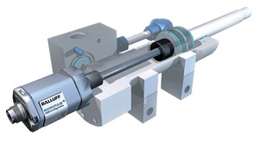
seals. It can also score the inside of the barrel and eventually ruin the cylinder.

If operating temperatures exceed 300° F, standard Buna-N nitrile rubber seals may fail. Viton synthetic rubber seals generally handle temperatures to 400° F and fluorocarbon seals even higher. When in doubt, assume conditions will be worse than they first appear.

10. Add a gland drain. Probably 90% of cylinder failures are due to the seals. That holds even if engineers specify the proper seals for the fluid, pressure, environment and application as they wear out over time and need replacement. Most experts recommend that seals should be maintained periodically, rather than waiting for failure at a usually inopportune time.

If cylinders are in hard-to-access locations that makes maintenance difficult, or if leaks will damage products or lead to costly downtime, order cylinders with a “gland drain.” This is a special port machined into the cylinder head between primary and secondary seals; or between primary and rod wiper. Then, if the primary rod seal begins to fail and leak, oil bypasses the seal and flows out the gland-drain port—generally through tubing to a collection bottle. If oil collects in the normally empty bottle, it gives a visual indication that seals are wearing out and will soon need replacement.

Cylinders usually have a secondary rod seal or a double-lip rod wiper that temporarily prevents oil from leaking out the rod end, giving maintenance personnel time to schedule repairs.

11. Watch the materials. The type of metal used for the cylinder head, base and bearing can make a significant difference. Most cylinders use SAE 660 bronze for rod bearings and medium-grade carbon steel for heads and bases, which is adequate for many applications. But stronger material, such as 65-45-12 ductile iron for rod bearings, can provide a sizable performance advantage for tough industrial tasks.

Also consider extreme temperatures. Typical carbon steels used in cylinder components are generally suited for around –5 to 200° F. In arctic conditions well below 0° F, for example, standard steel can become brittle and may require alternative materials.

12. Protect the rod. Because the piston rod meets the outside environment, it must resist attack from water, salt air, corrosives, and other harmful substances. In general industrial applications, carbon steel with chrome plating is the norm. But in wet or high humidity environments, such as marine hydraulics, 17-4PH stainless steel with chrome plating is used for most piston rods. Some cylinder manufacturers offer special protective coatings. Bosch Rexroth, for example, offers Enduroq, which is a proprietary thermal-spray coating or plasma-welded overlay that’s applied to rods for extreme corrosion protection and high wear resistance. It’s used in harsh environments, typically for specialty large-bore, long-stroke cylinders.

For dirty, abrasive conditions, engineers have a love/hate relationship with protective rod boots. Installing a boot over the rod keeps out dirt, metal shavings and other external contamination that would otherwise damage the rod and eventually the seals. However, if the boot punctures or rips, dirt gets drawn in and may not get out, which is worse than no boot at all. Maintenance personnel must routinely check for worn or torn boots that could accelerate damage to the cylinder.

Don’t overlook sizing software

Sizing software for cylinders is a great tool, but more engineers need to take advantage of the benefits it offers. These programs address most, if not all, of the pertinent questions designers need to answer to spec the right cylinder.

One such program developed by Bosch Rexroth is the Interactive Catalog System Rexroth-BR_Catalog2 (1)(www.boschrexroth.com/ics). It lets users enter parameters like force, pressure, load, angle of installation and mounting type, and the software sizes the cylinder, lists variations that meet the criteria and offers possible alternatives. It also lets engineers select and test cylinders on-screen before specifying the actual components. In addition, ICS generates dimensional drawings and 2D or 3D models for direct import into AutoCAD or other CAD software.

CMAFH Resources

Shop online for Rexroth hydraulic products here