Safety

The Emergence of Device-level Safety Communications in Manufacturing

Guest Contributor: Tom Knauer, Balluff

Manufacturing is rapidly changing, driven by trends such as low volume/high mix, shorter life cycles, changing labor dynamics and other global factors. One way industry is responding to these trends is by changing the way humans and machines safely work together, enabled by updated standards and new technologies including safety communications.

In the past, safety systems utilized hard-wired connections, often resulting in long cable runs, large wire bundles, difficult troubleshooting and inflexible designs. The more recent shift to safety networks addresses these issues and allows fast, secure and reliable communications between the various components in a safety control system. Another benefit of these communications systems is that they are key elements in implementing the Industrial Internet of Things (IIoT) and Industry 4.0 solutions.

Within a typical factory, there are three or more communications levels, including an Enterprise level (Ethernet), a Control level (Ethernet based industrial protocol) and a Device/sensor level (various technologies). The popularity of control and device level industrial communications for standard control systems has led to strong demand for similar safety communications solutions.

Safety architectures based on the most popular control level protocols are now common and often reside on the same physical media, thereby simplifying wiring and control schemes. The table, below, includes a list of the most common safety control level protocols with their Ethernet-based industrial “parent” protocols and the governing organizations:

Ethernet Based Safety Protocol Ethernet Based Control Protocol Governing Organization
CIP Safety Ethernet IP Open DeviceNet Vendor Association (ODVA)
PROFISafe PROFINET PROFIBUS and PROFINET International (PI)
Fail Safe over EtherCAT (FSoE) EtherCAT EtherCAT Technology Group
CC-Link IE Safety CC-Link IE CC-Link Partner Association
openSAFETY Ethernet POWERLINK Ethernet POWERLINK Standardization Group (EPSG)


These Ethernet-based safety protocols are high speed, can carry fairly large amounts of information and are excellent for exchanging data between higher level devices such as safety PLCs, drives, CNCs, HMIs, motion controllers, remote safety I/O and advanced safety devices. Ethernet is familiar to most customers, and these protocols are open and supported by many vendors and device suppliers – customers can create systems utilizing products from multiple suppliers. One drawback, however, is that devices compatible with one protocol are not compatible with other protocols, requiring vendors to offer multiple communication connection options for their devices. Other drawbacks include the high cost to connect, the need to use one IP address per connected device and strong influence by a single supplier over some protocols.

Device level safety protocols are fairly new and less common, and realize many of the same benefits as the Ethernet-based safety protocols while addressing some of the drawbacks. As with Ethernet protocols, a wide variety of safety devices can be connected (often from a range of suppliers), wiring and troubleshooting are simplified, and more data can be gathered than with hard wiring. The disadvantages are that they are usually slower, carry much less data and cover shorter distances than Ethernet protocols. On the other hand, device connections are physically smaller, much less expensive and do not use up IP addresses, allowing the integration into small, low cost devices including E-stops, safety switches, inductive safety sensors and simple safety light curtains.

Device level Safety Protocol Device level Standard Protocol Open or Proprietary Governing Organization
Safety Over IO-Link/IO-Link Safety* IO-Link Semi-open/Open Balluff/IO-Link Consortium
AS-Interface Safety at Work (ASISafe) AS-Interface (AS-I) Open AS-International
Flexi Loop Proprietary Sick GmbH
GuardLink Proprietary Rockwell Automation

* Safety Over IO-Link is the first implementation of safety and IO-Link. The specification for IO-Link Safety was released recently and devices are not yet available.

The awareness of, and the need for, device level safety communications will increase with the desire to more tightly integrate safety and standard sensors into control systems. This will be driven by the need to:

  • Reduce and simplify wiring
  • Add flexibility to scale up, down or change solutions
  • Improve troubleshooting
  • Mix of best-in-class components from a variety of suppliers to optimize solutions
  • Gather and distribute IIoT data upwards to higher level systems

Many users are realizing that neither an Ethernet-based safety protocol, nor a device level safety protocol can meet all their needs, especially if they are trying to implement a cost-effective, comprehensive safety solution which can also support their IIoT needs. This is where a safety communications master (or bridge) comes in – it can connect a device level safety protocol to a control level safety protocol, allowing low cost sensor connection and data gathering at the device level, and transmission of this data to the higher-level communications and control system.

An example of this architecture is Safety Over IO-Link on PROFISafe/PROFINET. Devices such as safety light curtains, E-stops and safety switches are connected to a “Safety Hub” which has implemented the Safety Over IO-Link protocol. This hub communicates via a “black channel” over a PROFINET/IO-Link Master to a PROFISafe PLC. The safety device connections are very simple and inexpensive (off the shelf cables & standard M12 connectors), and the more expensive (and more capable) Ethernet (PROFINET/PROFISafe) connections are only made where they are needed: at the masters, PLCs and other control level devices. And an added benefit is that standard and safety sensors can both connect through the PROFINET/IO-Link Master, simplifying the device level architecture.

Safety

Combining device level and control level protocols helps users optimize their safety communications solutions, balancing cost, data and speed requirements, and allows IIoT data to be gathered and distributed upwards to control and MES systems.

cropped-cmafh-logo-with-tagline-caps.pngCMA/Flodyne/Hydradyne is an authorized  Balluff distributor in Illinois, Wisconsin, Iowa and Northern Indiana.

In addition to distribution, we design and fabricate complete engineered systems, including hydraulic power units, electrical control panels, pneumatic panels & aluminum framing. Our advanced components and system solutions are found in a wide variety of industrial applications such as wind energy, solar energy, process control and more.

Testing and applying IEEE 1584’s new arc flash requirements

Guest contributor: Kevin J. Lippert, manager, codes & standards, Eaton

An arc flash analysis quantifies incident energy to better protect against an arc flash hazard. The latest updates to the Institute of Electrical and Electronics Engineers (IEEE) Std 1584TM 2018 Guide for Performing Arc Flash Calculations have made significant strides toward furthering electrical safety. The Guide, a widely accepted method for performing arc flash hazard calculations, is now backed by nearly 2000 additional tests — more than any other method — to provide the information necessary to complete an arc flash risk assessment.

Of course, arc flash analysis is never an exact science and, the use of IEEE 1584 is not mandatory. But I strongly recommend electrical engineers embrace the new version of IEEE 1584, as its formulas and mathematical models are based on a multitude of varied field conditions and the most up-to-date science.

New requirements lead to new questions

Consultants and electrical engineers have been using IEEE 1584 to calculate incident energy since the Guide’s inception in 2002. Many engineers have a comfort level with the 2002 version of the Guide and are very accustomed to its calculation methodologies, so they may have reservations about the 2018 version. Further, some professionals are beginning to raise questions as they apply the 2018 version in real-world scenarios.

Let’s take the new addition of electrode configuration as an example. Engineers have begun applying this aspect of the Guide on new projects, as data and equipment details are more likely available to meet the parameter needs of equations. However, these professionals question whether they have the same level of clarity for older systems and existing projects. In these cases, electrode configurations and box dimensions may be unclear or very difficult to ascertain, making the implementation of the 2018 version questionable for existing systems. Some engineers have indicated they would revert to the 2002 version in such instances.

Situations vary, so toggling between the 2002 and 2018 calculations may sometimes seem logical, but in practice, doing so creates confusion. At Eaton, we think it is important to eliminate that confusion.

Clarifying requirements through independent studies

Our mission is to help professionals adopt the 2018 Guide and increase confidence in their data and calculation results. Today, my engineering colleagues at Eaton use updated IEEE 1584 equations to model electrical systems and perform sample calculations to define the differences between the 2002 and 2018 versions.
Our mission is to help consultants and electrical engineers understand and adopt the 2018 Guide and increase confidence in their data and calculation results.

With each new power distribution system model, we gain a better understanding of the increases and decreases of incident energy value applications calculated from the 2002 version and recommend how to apply the updated Guide moving forward.
Our preliminary findings suggest:

  • Three additional electrode configurations — vertical electrodes (metal box with an insulating barrier (VCBB)), horizontal electrodes (metal box (HCB)) and horizontal electrodes (open air (HOA)) — represent perhaps the most significant changes to the Guide. Generally, the horizontal electrode configurations result in higher calculated incident energy than the vertical configurations.
  • The Guide now accounts for engineered electrical assemblies and tests to North American ANSI/IEEE Standards and those in other world regions thanks to higher calculated arcing current values in the 2018 version. We also see an increase in incident energy values. We believe one of the reasons this occurs is because the 2018 update offers more selection options for phase conductor spacing.
  • Additional options for enclosure size are now available, allowing for more accurate modeling based on actual equipment conditions. In most cases, larger enclosures result in slightly lower incident energies as plasma arc events partially dissipate in voluminous enclosures.

How to account for real-world applications

While preliminary, I expect our findings to impact many field applications. Topping the list is additional training that may be required to perform surveys, collect data and complete accurate calculations due to the sheer number of alternatives and variables to consider. In my opinion, consultants and electrical engineers should prepare for significant procedural changes:

  • Higher arcing currents calculated using the 2018 Guide could be offset by faster clearing times of the overcurrent protective device (OCPD). Higher currents mean a better chance that protective devices will operate in the instantaneous region and result in faster clearing times. This may offer lower calculated incident energies than the 2002 version, which has a lower arcing current but a longer clearing time.
  • Engineers should pay close attention to time-current characteristic (TCC) curves and work to understand relationships between arcing currents and clearing times based on protective device selection and the many settings available.
  • The 2018 Guide is not definitive in suggesting a 240V low-end threshold for system analysis, stating only that sustainable arcs are less likely but possible in systems with available short circuit currents of 2000A or less. The former Guide defined a low-end for analysis stating that equipment below 240V not be considered unless it involves at least one 125kVA transformer or larger.
  • There is a gap in the methodology used to establish bus configurations for equipment. Clarity and direction should be provided in an application-style guide to help manufacturers and power system engineers understand configurations that apply to diverse electrical components and assemblies.

Implement IEEE 1584 across all systems

I believe consultants and electrical engineers should embrace and begin using the 2018 edition of IEEE 1584 moving forward. As with any new change in engineering practice, I expect an adjustment period during which professionals will acclimate to the Guide’s new calculations. Further, while IEEE 1584 is not a mandatory requirement, I believe more users will accept how the updated Guide enhances safety across all electrical systems, both existing and new:

Existing equipment

If you’ve changed your OCPD, its settings, or are approaching the five-year update threshold mandated by National Fire Protection Association (NFPA) 70E Section 130.5(G), calculating incident energy based on IEEE 1584 makes great sense because its models are based on the most current data available.

New equipment

Higher incident energy calculations should cause users to look for alternative methods of reducing arc flash risk. We’ve determined that some IEEE 1584 calculated incident energies are higher. As a result, engineering controls such as arc reduction maintenance switches and arc quenching technologies will mitigate the risk of increased arc flash energies. Design engineers should take it upon themselves to understand the options of engineering controls to reduce or eliminate the risk of arc flash events.

cropped-cmafh-logo-with-tagline-caps.png

CMA/Flodyne/Hydradyne is an authorized  Eaton Electrical distributor in Illinois, Wisconsin, Iowa and Northern Indiana.

In addition to distribution, we design and fabricate complete engineered systems, including hydraulic power units, electrical control panels, pneumatic panels & aluminum framing. Our advanced components and system solutions are found in a wide variety of industrial applications such as wind energy, solar energy, process control and more.

Safety Over IO-Link Helps Enable Human-Robot Collaboration

Guest Contributor: Tom Knauer, Balluff

Safety Over IO-Link makes it easier to align a robot’s restricted and safeguarded spaces, simplifies creation of more dynamic safety zones and allows creation of “layers” of sensors around a robot work area.

For the past several years, “collaboration” has been a hot topic in robotics.  The idea is that humans and robots can work closely together, in a safe and productive manner.  Changes in technology and standards have created the environment for this close cooperation. These standards call out four collaborative modes of operation: Power & Force Limiting, Hand Guiding, Safety Rated Monitored Stop, and Speed & Separation Monitoring (these are defined in ISO/TS 15066).

Power & Force Limiting

Power & Force Limiting is what many people refer to when speaking about Collaborative Robots, and it applies to robots such as Baxter from Rethink Robotics and the UR series made by Universal Robots.  While the growth in this segment has been fast, there are projections that traditional robots will continue to make up 2/3 of the market through 2025, which means that many users will want to improve their traditional robot solutions to “collaborate”.

Hand Guiding

Hand guiding is the least commonly applied mode, it is used for very specific applications such as power assist (one example is loading spare tires into a new car). It generally requires special equipment mounted on the robot to facilitate the guiding function.

Safety Rated Monitored Stop and Speed & Separation Monitoring

Safety Rated Monitored Stop and Speed & Separation Monitoring are especially interesting for traditional robots, and require safety sensors and controls to be implemented.  Customers wanting closer human-robot collaboration using traditional robots will need devices such as safety laser scanners, safety position sensors, safety PLCs and even safety networks – this is where Safety Over IO-Link can enable collaborative applications.

SAfety

Many of IO-Link’s well-known features also provide advantages for traditional robot builders and users:

1) Faster & cheaper integration/startup through reduction in cabling, standardized connectors/cables/sensors and device parameterization.

2) Better connection between sensors and controllers supports robot supplier implementation of IIoT and improved collaboration by making it easier to gather process, device and event data – this allows improved productivity/uptime, better troubleshooting, safer machines, preventative maintenance, etc.

3) Easier alignment of the robot’s restricted and safeguarded spaces, simplifying creation of more dynamic safety zones to support closer human-robot collaboration.

The third item is especially relevant in enabling collaborative operation of traditional robots.  The updated standards allow the creation of a “shared workspace” for the robot and human, and how they interact in this space depends on the collaborative mode.  At a simple level, Safety Rated Monitored Stop and Speed & Separation Monitoringrequire this “shared workspace” to be monitored, this is generally accomplished using a “restricted space” and a “safeguarded space.”  These “spaces” must be monitored using many sensors, both inside and outside the robot.

First, the robot’s “restricted space” is set up to limit the robot’s motion to a specific 3-dimensional volume.  In the past, this was set up through hard stops, limit switches or sensors, more recently the ANSI RIA R15.06 robot standard was updated to allow this to be done in software through safety-rated soft axis and space limiting.  Most robot suppliers offer a software tool such as “Safe Move” or Dual Check Safety” to allow the robot to monitor its own position and confirm it is where it is supposed to be.  This feature requires safe position feedback and many sensors built into the robot.  This space can change dynamically with the robot’s program, allowing more flexibility to safely move the robot and assure its location.

Second, a safeguarded space must be defined and monitored.  This is monitored using safety rated sensors to track the position of people and equipment around the robot and send stop (and in some cases warning) signals to the safety controller and robot.  Safety Over IO-Link helps connect and manage the safety devices, and quickly send their signals to the control system.

In the past, integrating a robot with safety meant wiring many safety sensors with long cable runs and many terminations back to a central cabinet.  This was a time consuming, labor intensive process with risk of miswiring or broken cables.  IO-Link significantly reduces the cost, speed and length of connections due to use of standard cables and connectors, and the network approach.  It is also much simpler for customers to change their layout using the network, master & hub approach.

Customers wanting collaborative capability in traditional robots will find that Safety Over IO-Link can significantly simplify and reduce the cost of the process of integrating the many advanced safety sensors into the application.

To learn more, visit www.balluff.com.

cropped-cmafh-logo-with-tagline-caps.pngCMA/Flodyne/Hydradyne is an authorized  Balluff distributor in Illinois, Wisconsin, Iowa and Northern Indiana.

In addition to distribution, we design and fabricate complete engineered systems, including hydraulic power units, electrical control panels, pneumatic panels & aluminum framing. Our advanced components and system solutions are found in a wide variety of industrial applications such as wind energy, solar energy, process control and more.

Robot Collaborative Operation

Guest contributor: Tom Knauer, Balluff

In previous blogs, we discussed how “Safety Over IO-Link Helps Enable Human-Robot Collaboration” and “Safety & Productivity”. We’ll build on these blogs and dive more deeply into two robot collaborative operating modes: Safety-Rated Monitored Stop (SRMS) and Speed & Separation Monitoring (SSM).

Human-Robot Collaboration

Human-robot collaboration has received a lot of attention in the media, yet there is still confusion about the meaning and benefits of various types of collaboration. In a previous blog we briefly discussed the four collaborative modes defined by the global standard ISO/TS 15066. The most well-known mode is “power & force limiting”, which includes robots made by Universal Robots and Rethink. As the name implies, these robots are designed with limited power and force (and other ergonomic factors) to avoid injury or damage, but they are also slower, less precise and less powerful than traditional robots, reducing their usefulness in many common applications.

Tom-K-Blog-768x267

The safety-rated monitored stop (SRMS) and speed & separation monitoring (SSM) modes are very interesting because they allow larger, more powerful, traditional robots to be used collaboratively — though in a different manner than power & force limited robots. The updated standards allow the creation of a shared workspace for the robot and human and define how they may interact in this space. Both SRMS and SSM require this shared workspace to be monitored using advanced safety sensors and software, which create a restricted space and a safeguarded space. With SRMS, the robot stops before the operator enters the collaborative workspace — this requires a safety sensor to detect the operator. Similarly, in SSM the goal is to control the separation distance between the human and robot, but it can be dynamic, rather than static as in SRMS. The SRMS separation distance can never be less than the protective distance and this requires sensors to verify the separation.

Spaces

The robot’s restricted space is a 3-dimensional area created to limit where the robot can operate. In the past this was done through limit switches, hard stops or sensors such as Balluff’s BNS; now the standards have been updated to allow this to be done in software with internal robot feedback that can dynamically change to adapt to the robot’s programmed operation. The robot controller can now restrict the robot’s motion to a specific envelope and monitor its actual position against its programmed position within this envelope using software tools such as Safe Move or Dual Check Safety.

The safeguarded space is defined and monitored using safety sensors. The robot might know and assure its own safe position within the restricted space, but it doesn’t know whether or not a person or obstruction is in this space, therefore a safeguarded space needs to be created using safety sensors. Advanced sensors not only detect people or obstructions, but can also actively track their position around the robot and send warning or stop signals to the safety controller and robot. Safety laser scanners, 3D safety cameras and other safety sensors can create zones, which can also be dynamically switched depending on the operating state of the robot or machine.

Closely coordinating the restricted space and safeguarded space creates a flexible and highly productive system. The robot can operate in one zone, while an operator loads/unloads in a different zone. The robot sensors monitor the restricted space while the safety sensors monitor the safeguarded space – and when the robot moves to the next phase of operation, these can dynamically switch to new zones. Warning zones can also be defined to cause the robot can slow down if someone starts to approach too closely and then stop if the person comes too close.

Blog_graphic_Safe-space_081718-01

System Linkages

Linking the restricted space and safeguarded space to create an effective, closely coordinated human-robot SSM/SRMS collaborative system requires several elements: a high performance robot and controller with advanced software (e.g. Safe Move), a fieldbus and a variety of built-in and external sensors (standard and safety).

Significant growth in robot collaborative applications utilizing safety-rated monitored stop (SRMS) and speed & separation monitoring (SSM) will occur as robot users strive to improve productivity and safety of traditional robot systems – especially in applications requiring faster speed, higher force and more precision than that offered by power & force limited robots.

To learn more visit www.balluff.com

cropped-cmafh-logo-with-tagline-caps.pngCMA/Flodyne/Hydradyne is an authorized  Balluff distributor in Illinois, Wisconsin, Iowa and Northern Indiana.

In addition to distribution, we design and fabricate complete engineered systems, including hydraulic power units, electrical control panels, pneumatic panels & aluminum framing. Our advanced components and system solutions are found in a wide variety of industrial applications such as wind energy, solar energy, process control and more.

Changing the Paradigm from Safety vs. Productivity to Safety & Productivity

Guest Contributor: Tom Knauer, Balluff

In a previous blog, we discussed how “Safety Over IO-Link Helps Enable Human-Robot Collaboration”. It was a fairly narrow discussion of collaborative robot modes and how sensors and networks can make it easier to implement these modes and applications. This new blog takes a broader look at the critical role safety plays in the intersection between the machine and the user.

In the past, the machine guarding philosophy was to completely separate the human from the machine or robot.  Unfortunately, this resulted in the paradigm of “safety vs. productivity” — you either had safety or productivity, but you couldn’t have both. This paradigm is now shifting to “safety & productivity”, driven by a combination of updated standards and new technologies which allow closer human-machine interaction and new modes of collaborative operation.

Tom_Safety1.png
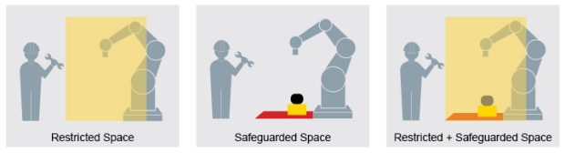
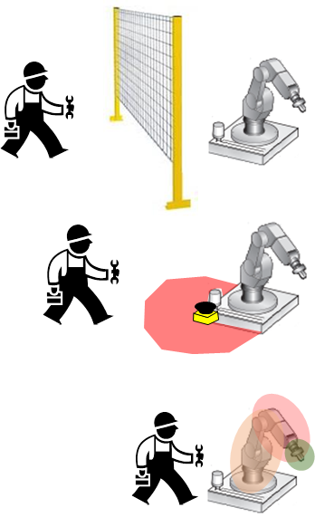
The typical machine/robot guarding scheme of the past used fences or hard guards to separate the human from the machine.  Doors were controlled with safety interlock switches, which required the machine to stop on access, such as to load/unload parts or to perform maintenance or service, and this reduced productivity.  It was also not 100% effective because workers inside a machine area or work cell might not be detected if another worker restarted the stopped machine.  Other drawbacks included the cost of space, guarding, installation, and difficultly changing the work cell layout once hard guarding had been installed.

We’ve now come to an era when our technology and standards allow improved human access to the machine and robot cell.  We’re starting to think about the human working near or even with the machine/robot. The robot and machinery standards have undergone several changes in recent years and now allow new modes of operation.  These have combined with new safety technologies to create a wave of robot and automation suppliers offering new robots, controllers, safety and other accessories.

Standards
Machine and robot safety standards have undergone rapid change in recent years. Standard IEC 61508, and the related machinery standards EN/ISO 13849-1 and EN/IEC 62061, take a functional approach to safety and define new safety performance levels. This means they focus more on the functions needed to reduce each risk and the level of performance required for each function, and less on selection of safety components. These standards helped define, and made it simpler and more beneficial, to apply safety PLCs and advanced safety components. There have also been developments in standards related to safe motion (61800-5-2) which now allow more flexible modes of motion under closely controlled conditions. And the robot standards (10218, ANSI RIA 15.06, TS15066) have made major advances to allow safety-rated soft axes, space limiting and collaborative modes of operation.

Technology
On the technology side, innovations in sensors, controllers and drives have changed the way humans interact with machines and enabled much closer, more coordinated and safer operation. Advanced sensors, such as safety laser scanners and 3D safety cameras, allow creation of work cells with zones, which makes it possible for an operator to be allowed in one zone while the robot performs tasks in a different zone nearby. Controllers now integrate PLC, safety, motion control and other functions, allowing fast and precise control of the process. And drives/motion systems now operate in various modes which can limit speed, torque, direction, etc. in certain modes or if someone is detected nearby.

Sensors and Networks
The monitoring of these robots, machines and “spaces” requires many standard and safety sensors, both inside and outside the machine or robot. But having a lot of sensors does not necessarily allow the shift from “productivity vs. safety” to “productivity & safety” — this requires a closely coordinated and integrated system, including the ability to monitor and link the “restricted space” and “safeguarded space.” This is where field busses and device-level networks can enable tight integration of devices with the control system. IO-Link masters and Safety Over IO-Link hubs allow the connection of a large number of devices to higher level field busses (ProfiNet/ProfiSafe) with effortless device connection using off-the-shelf, non-shielded cables and connectors.

Balluff offers a wide range of solutions for robot and machine monitoring, including a broad safety device portfolio which includes safety light curtains, safety switches, inductive safety sensors, an emergency stop device and a safety hub. Our sensors and networks support the shift to include safety without sacrificing productivity.

To learn more about Safety over IO-Link, visit www.balluff.com

cropped-cmafh-logo-with-tagline-caps.pngCMA/Flodyne/Hydradyne is an authorized  Balluff distributor in Illinois, Wisconsin, Iowa and Northern Indiana.

In addition to distribution, we design and fabricate complete engineered systems, including hydraulic power units, electrical control panels, pneumatic panels & aluminum framing. Our advanced components and system solutions are found in a wide variety of industrial applications such as wind energy, solar energy, process control and more.

What Exactly is Safety Over IO-Link?

Automation Pyramid.png

This integrated safety concept is the logical continuation of the IO-Link philosophy. It is the only globally available technology to build on the proven IO-Link standards and profisafe. This means it uses the essential IO-Link benefits such as simple data transport and information exchange, high flexibility and universal applicability for safety signals as well. Safety over IO-Link combines automation and safety and represents efficient safety concepts in one system. Best of all, the functionality of the overall system remains unchanged. Safety is provided nearly as an add-on.

In the center of this safety concept is the new safety hub, which is connected to an available port on an IO-Link master. The safety components are connected to it using M12 standard cable. The safety profisafe signals are then tunneled to the controller through an IO-Link master. This has the advantage of allowing existing infrastructure to still be used without any changes. Parameters are configured centrally through the user interface of the controller.

Safety Hub

The safety hub has four 2-channel safe inputs for collecting safety signals, two safe outputs for turning off safety actuators, and two multi-channel ports for connecting things like safety interlocks which require both input and output signals to be processed simultaneously. The system is TÜV- and PNO-certified and can be used up to PLe/SIL 3. Safety components from all manufacturers can be connected to the safe I/O module.

Like IO-Link in general, Safety over IO-Link is characterized by simple system construction, time-and cost-saving wiring using M12 connectors, reduction in control cabinet volume and leaner system concepts. Virtually any network topology can be simply scaled with Safety over IO-Link, whereby the relative share of automation and safety can be varied as desired. Safety over IO-Link also means unlimited flexibility. Thanks to varying port configuration and simple configuration systems, it can be changed even at the last minute. All of this helps reduce costs. Additional savings come from the simple duplication of (PLC-) projects, prewiring of machine segments and short downtimes made possible by ease of component replacement.

Development of IO-Link, number of sold nodes.png

To learn more about Safety over IO-Link, visit www.balluff.com

cropped-cmafh-logo-with-tagline-caps.pngCMA/Flodyne/Hydradyne is an authorized  Balluff distributor in Illinois, Wisconsin, Iowa and Northern Indiana.

In addition to distribution, we design and fabricate complete engineered systems, including hydraulic power units, electrical control panels, pneumatic panels & aluminum framing. Our advanced components and system solutions are found in a wide variety of industrial applications such as wind energy, solar energy, process control and more.

Improving Arc Flash Prevention and Safety

Guest contributor: Steve Sullivan, Rittal

Working among the electrical components in an enclosure comes with inherent risks. The power in any one enclosure can range from 2kw up to 200kw depending on the power density. One of the most common and dangerous risk is an arc flash (or flashover).

When an explosive release of energy erupts from a phase-to-phase or phase-to-ground arc fault the results range from devastating to deadly. This air to ground electrical explosion is a critical concern for engineers and managers who are charged with the safety of their employees.

The Destructive Force of an Arc Flash

The dangers from an arc flash are all too well known. Five to 10 of these accidents occur every day in the United States. When metal expands and vaporizes at the fault, it causes extreme heating of the air, upwards of 10,000°C/18,032°F. The concussive pressure wave can knock personnel off their feet, the ultraviolet light flash can cause blindness, the sound blast, deafness and the molten metal and heat can cause second and third degree burns. The specific death toll has been estimated to be up to 1-2 people per day worldwide.

An arc flash can be the result of unsafe work procedures, accidental contact or more systemic problems such as corrosion of components and connections or insulation failure. Arc flash prevention should be incorporated into any application from the beginning of the design process.

Minimizing Arc Flash Exposure

Design and retrofit approaches can limit exposure by using components installed outside the enclosure to permit qualified personnel in personal protective equipment (PPE) to service equipment inside without opening the enclosure door. Interface flaps and window kits permit data retrieval, equipment monitoring or routine maintenance to be performed from outside. Collapsible fold down shelves be raised for use with laptops and monitoring equipment. External data pockets can hold wiring diagrams, operation manuals and other documents.

Rittal and Arc Flash Protection

Sometimes components must be accessed from inside the enclosure. Rittal’s arc flash solution is designed to keep high and low voltage equipment within the confines of their own respective enclosures. Low voltage enclosures house equipment that is used for programming, data acquisition and system adjustment.

High voltage components are isolated within their own disconnect enclosure, while line side power is segregated within the power isolation enclosure. A partition wall acts as a barrier to high voltage line side power. Rittal’s interlocking door system ensures that the high voltage enclosure cannot be opened while the disconnect switch is in “ON” position.

For additional safety, all interlocked doors and master door must be closed in order to re-energize the enclosure. This removes potential for accidental contact with the inline power when the disconnect enclosure is put in a safe power-off position, and locked and tagged out.

Minimizing exposure to line side power can help protect personnel from accidents. A qualified person wearing PPE and following appropriate safe work practices can perform visual inspections and tasks, such as diagnosis, testing, troubleshooting and voltage measurement with the door open even when the main enclosure is energized.

Rittal offers an unlimited choice of low-voltage and high-voltage enclosure combinations. More important than saving down time caused by having to power down the whole system to service, the Rittal arc flash solution helps to decrease the risk personnel being exposed to arc flash-related injuries.

Safety is always your priority, so download Rittal’s Arc Flash and How to Prevent it whitepaper for the first step towards arc flash prevention.

About Us

cropped-cmafh-logo-with-tagline-caps.png

CMA/Flodyne/Hydradyne is an authorized  Rittal distributor in Illinois, Wisconsin, Iowa and Northern Indiana.

In addition to distribution, we design and fabricate complete engineered systems, including hydraulic power units, electrical control panels, pneumatic panels & aluminum framing. Our advanced components and system solutions are found in a wide variety of industrial applications such as wind energy, solar energy, process control and more.