What is the first thing that comes to mind if someone says “proximity sensor?” My guess is the inductive sensor, and justly so because it is the most used sensor in automation today. There are other technologies that use the term proximity in describing the sensing mode, including diffuse or proximity photoelectric sensors that use the reflectivity of the object to change states and proximity mode of ultrasonic sensors that use high-frequency sound waves to detect objects. All these sensors detect objects that are in close proximity to the sensor without making physical contact. One of the most overlooked or forgotten proximity sensors on the market today is the capacitive sensor.
Capacitive sensors are suitable for solving numerous applications. These sensors can be used to detect objects, such as glass, wood, paper, plastic, or ceramic, regardless of material color, texture, or finish. The list goes on and on. Since capacitive sensors can detect virtually anything, they can detect levels of liquids including water, oil, glue, and so forth, and they can detect levels of solids like plastic granules, soap powder, sand, and just about anything else. Levels can be detected either directly, when the sensor touches the medium, or indirectly when it senses the medium through a non-metallic container wall.
Capacitive sensors overview
Like any other sensor, there are certain considerations to account for when applying capacitive, multipurpose sensors, including:
1 – Target
Capacitive sensors can detect virtually any material.
The target material’s dielectric constant determines the reduction factor of the sensor. Metal / Water > Wood > Plastic > Paper.
The target size must be equal to or larger than the sensor face.
2 – Sensing distance
The rated sensing distance, or what you see in a catalog, is based on a mild steel target that is the same size as the sensor face.
The effective sensing distance considers mounting, supply voltage, and temperature. It is adjusted by the integral potentiometer or other means.
Additional influences that affect the sensing distance are the sensor housing shape, sensor face size, and the mounting style of the sensor (flush, non-flush).
3 – Environment
Temperatures from 160 to 180°F require special considerations. The high-temperature version sensors should be used in applications above this value.
Wet or very humid applications can cause false positives if the dielectric strength of the target is low.
In most instances, dust or material buildup can be tuned out if the target dielectric is higher than the dust contamination.
4 – Mounting
Installing capacitive sensors is very similar to installing inductive sensors. Flush sensors can be installed flush to the surrounding material. The distance between the sensors is two times the diameter of the sensing distance.
Non-flush sensors must have a free area around the sensor at least one diameter of the sensor or the sensing distance.
5 – Connector
Quick disconnect – M8 or M12.
Potted cable.
6 – Sensor
The sensor sensing area or face must be smaller or equal to the target material.
Maximum sensing distance is measured on metal – reduction factor will influence all sensing distances.
Use flush versions to reduce the effects of the surrounding material. Some plastic sensors will have a reduced sensing range when embedded in metal. Use a flush stainless-steel body to get the full sensing range.
These are just a few things to keep in mind when applying capacitive sensors. There is not “a” capacitive sensor application – but there are many which can be solved cost-effectively and reliably with these sensors.
In addition to distribution, we design and fabricate complete engineered systems, including hydraulic power units, electrical control panels, pneumatic panels & aluminum framing. Our advanced components and system solutions are found in a wide variety of industrial applications such as wind energy, solar energy, process control and more.
IIOT (Industrial internet of things) has gained much traction and attraction in past years. With industries getting their assets online for monitoring purposes and new IO-Link sensors providing a ton of information on a single package, monitoring machines has become economically feasible.
Vibration is one of the most critical metrics regarding the health of machines, providing early detection of potential faults – before they cause damage or equipment failure. But since this is a relatively new field and use case, there is not much information about it. Most customers are confused about where to start. They want a baseline to begin monitoring machines and then finetune them to their use case.
“Vibration is one of the most critical metrics regarding the health of machines…”
One approach to solve this is to hire a vibration expert to determine the baseline and the best location to mount the vibration measuring sensor. Proper setup increases the threshold of getting into condition monitoring as a new user figures out the feasibility of such systems.
I direct my customers to this standardized baseline chart from ISO, so they can determine their own baselines and the best mounting positions for their sensors. The table shows the different standards for severity for different machine classes. These standards detail the baseline vibration and show the best place to mount the sensor based on the machine type.
Click here for more information on the benefits of condition monitoring.
In addition to distribution, we design and fabricate complete engineered systems, including hydraulic power units, electrical control panels, pneumatic panels & aluminum framing. Our advanced components and system solutions are found in a wide variety of industrial applications such as wind energy, solar energy, process control and more.
Guest contributor: John Tackacs, BalluffTires being transported between the curing presses and the staging area before their final inspection often become clustered together. This jam up can cause imperfections to the tires and damage to the conveyors. To alleviate this problem, some tire manufacturers have installed vision systems on their conveyors to provide visual feedback to their production and quality teams, and alert them when the tires start to get too close together.
A vision system can show you alerts back in your HMI by using inputs and outputs built into the camera or use an IO-Link port on the camera to attach a visual display, for example a SmartLight with audible and flashing alerts enabled. Once you see these alerts, the PLC can easily fix the issue from the program or a maintenance worker or engineer can quickly respond to the alert.
Widespread use of smart vision cameras with various pixel options has become a trend in tire manufacturing. In additional to giving an early alert to bunching problems, vision systems can also capture pictures and data to verify that tires were cleared all the way into final inspection. Although tire machine builders are being asked to incorporate vision systems into their machines during the integration process, it is more likely for systems to be added in plants at the application level.
Vision systems can improve production throughput, quality issues and record production data about the process for analytics and analysis down the road. Remember a tire plant usually consists of these processes in their own large section of the plant and involves many machines in each section:
Mixing
Tire Prep
Tire Build
Curing
Final Inspection
Each one of these process areas in a plant can benefit from the addition of vision systems. Here are a few examples:
Mixing areas can use cameras as they mill rubber and detect when rubber sheets are off the rollers and to look for engraved information embedded in the rubber material for logistics and material flow to the proper processes.
Tire Prep can use cameras to ensure all the different strand colors of steel cords are embedded or painted on the rubber plies before going to tire build process.
Tire Build can use vision to detect the side-wall beads are facing the right direction and reading the embedded position arrows on the beads before tire plies are wrapped around them.
Curing area can use vision to monitor tire clusters on conveyors and make sure they are not too close to each other by using the measuring tool in the camera software.
Final Inspection can use vision to read barcodes, QR codes, detect colors of embossed or engraved serial numbers, detect different color markings and shape of the markings on the tire.
The use of machine vision systems can decrease quality issues by pinpointing errors before they make it through the entire production process without detection.
In addition to distribution, we design and fabricate complete engineered systems, including hydraulic power units, electrical control panels, pneumatic panels & aluminum framing. Our advanced components and system solutions are found in a wide variety of industrial applications such as wind energy, solar energy, process control and more.
Manufacturers of mobile equipment are tasked with the never-ending pursuit of making their machines more productive while adhering to the latest safety regulations, and all at less cost. To help achieve these goals, machines today use electronic control modules to process inputs and provide outputs that ultimately control the machine functions. Yet with all the changes in recent years, one component left over from that earlier era remains in regular use — the mechanical switch. Switches offered a variety of levers, rollers, and wands for actuation, and many were sealed for an IP67 rating for outdoor use, but they came with an array of problems, including damaged levers, contact corrosion, arcing concerns, dirt or grain dust ingress, and other environmental hazards. Still, overall they were an acceptable and inexpensive way to receive position feedback for on/off functions.
Today, mechanical switches can still be found on machines used for boom presence, turret location, and other discrete functions. But are they the right product for today’s machines?
The original design parameters may have required the switch to drive the load directly, and therefore a rating of 10A@240V might be a good design choice for the relay/diode logic circuits of the past. But a newly designed machine may be switching mere milliamps through the switch into the control module. Does the legacy switch have the proper contact plating material for the load today? Switches use rare metals such as rhodium, palladium, platinum, gold, and silver in attempts to keep the contact resistance low and to protect those contacts from corrosion. Consequently, as China pursues Nonroad Stage IV standards, these metals, some also used in catalytic converters, have sharply increased in price, leading to substantial cost increases to switch manufacturers and ultimately switch users.
A better approach to position feedback for today’s mobile machines is the inductive position sensor. Inductive sensors offer a sealed, non-contact alternative to mechanical switches. Sensing ferrous and non-ferrous metals without physical contact, they eliminate many of the field problems of the past, and non-metallic substances such as water, dirt, and grain dust, do not affect the operation. These qualities make the sensor very suitable for the harsh conditions found in agricultural and construction environments.
Inductive proximity sensors come in a variety of form factors:
Threaded cylindrical – With zinc-plated brass or stainless-steel housings, the threaded barrel styles are popular for their ease of mounting and gap adjustment.
Low profile rectangular – These “flatpack” style sensors are great under seats for operator presence.
Block designs – The compact, cubed package is ideal for larger sensing ranges.
Large cylindrical – These large “pancake” style sensors are great for detecting suspension movements and other applications requiring extreme ranges.
Inductive position sensors are more than just a discrete product used for detecting linkage, operator presence, or turret stops; They can also perform the duties of a speed sensor by counting teeth (or holes) to determine the RPM of a rotating shaft. Other models offer analog outputs to provide a continuous feedback signal based on the linear location of a metal linkage or lever. Safety rated outputs, high temperatures, and hazardous area options are some of the many product variants available with this electromagnetic technology.
So, perhaps it’s time to review that legacy switch and consider an inductive sensor?
To learn how an inductive position sensor performs its magic, please take a look at an earlier blog:
In addition to distribution, we design and fabricate complete engineered systems, including hydraulic power units, electrical control panels, pneumatic panels & aluminum framing. Our advanced components and system solutions are found in a wide variety of industrial applications such as wind energy, solar energy, process control and more.
Hydraulic valves: Directional valve with integrated digital axis controller
What are the current market requirements for hydraulic valves?
We are currently experiencing a transition from classic, analogous hydraulics to connectable digital fluid technology. European machine manufacturers in particular are increasingly digitizing their machine designs and expect that hydraulics can be seamlessly embedded into these connected environments. This means that regarding the level of automation, hydraulics are on a par with electromechanical drives. One of the decisive features in this respect is the seamless integration of intelligent hydraulic valves into different automation topologies via open standards such as multiple Ethernet interfaces.
Which new technical possibilities are available to meet these requirements?
Smart single-axis controllers are already remotely regulating hydraulic motions in a closed control loop. In addition, a powerful motion control is integrated into the on-board electronics of the valve. It performs the target-actual comparison on site and regulates accurately to a few micrometers. The control quality of the system is exclusively determined by the resolution of the measurement systems. These motion controls without control cabinet are increasingly used in saw lines, paper mills and machine tools. In addition, there are smart variable speed pump drives and smart pump controls. They provide completely new possibilities of replacing the throttle controls, which were predominantly used up to now, by more energy-efficient displacement controls. In this way, functions which were previously executed by valves are relocated to the software.
What about the integration of sensor technology into hydraulic valves?
The mass production of sensors for the automotive or the consumer products industry has significantly reduced the costs. Now, sensors are increasingly used in hydraulics. In our opinion, the integration of sensor technology of this kind into existing valve housings is the next step. Regarding condition monitoring, sensors could collect information on fluid quality, temperature, vibrations and performed switching cycles. Via deep learning algorithms, users can then detect wear before it causes malfunction.
Which other possibilities of mechanization does a valve provide?
The degree of freedom regarding connection geometries is already limited by standard requirements. The hydraulics industry discussed the topic of digital hydraulics in great depth some time ago. The idea was and is to control flows in a “stepped” or “clocked” way using single- or multi-bit strategies. In certain applications, this can constitute an advantage compared to continuously variable technology.
Which other innovations in hydraulic valves are relevant in your company?
It is no longer a question whether hydraulic valve technology will benefit from connectivity or not. The only question is when. The current discussions around Industry 4.0 clearly show how important it is to define all required functions and functionalities. Only if mechanisms and sensor technology are standardized across different manufacturers will active connectivity and communication be possible. Even in the future, not every hydraulic-mechanical pressure valve will have digital electronics on board or be connected to a control system or other valves. An imprinted QR code with information on the manufacturer’s settings, functional descriptions or information on replacement seals are a first step towards connectivity. In the area of new materials and production technologies, Rexroth has many innovations in the pipeline. 3D printing of cores for cast housings or direct printing considerably lowers energy consumption during the operation of valves. While the divisibility of the core mold had to be taken into account in the design of the core, this is no longer necessary today thanks to core printing. This means that we can use other channel designs which allow for lower pressure losses and improve energy consumption. For a valve with a flow of 10,000 l/min, the reduction of flow resistance by 10 to 20 percent significantly reduces the operating expenses.
How do these trends affect your products?
With the IAC (integrated axis controller) valves, Bosch Rexroth offers motion control without control cabinet which is completely integrated into valve electronics. It can be fully connected via open interfaces. The same applies to servo-hydraulic axes with their own fluid circuit. In these ready-to-mount axes, pump, valves and cylinders form an assembly to which the machine manufacturer only has to connect power supply and control communication. They use the same commissioning tools and user interfaces which means that all drive technologies provide the same look and feel. Classic servo valves, however, can also be improved further. New plug-in amplifiers with pulse width modulation for on/off valves by Rexroth reduce the surface temperature of the connectors by more than 80 degrees to only 50 degrees. This is particularly interesting for saw lines where easily inflammable sawdust constitutes an explosion hazard.
Outlook: How will valve technology change in the next 10 years?
In 10 years, valves will allow for easier project planning, more comfortable commissioning and more efficient operation and will provide more information before a service case. If service is required, the valve may already have ordered its spare parts.
In addition to distribution, we design and fabricate complete engineered systems, including hydraulic power units, electrical control panels, pneumatic panels & aluminum framing. Our advanced components and system solutions are found in a wide variety of industrial applications such as wind energy, solar energy, process control and more.
Photoelectric sensors with laser and red-light are widely used in all areas of industrial automation. A clean, dust-free and dry environment is usually essential for the proper operation of photoeyes, however, they can be the best choice in many dirty and harsh applications. Examples of this are raw steel production in steel mills and further metallurgical processes down to casting and hot-rolling.
Cutting of billets at casting – Photo: M.Münzl
Photoelectric sensors are especially useful in these environments thanks to their long sensing distance and their ability to detect objects independent of their material.
Most photoelectric sensors are approved to work in ambient temperatures of 55 to 60 °C. The maximum temperature range of these sensors is most often limited by the specifications of the optical components of the sensor, like the laser-diodes, but by taking certain precautions photoelectric sensors can provide optimal use in much hotter applications.
Maximize the distance In steel production many parts of the process are accompanied by high ambient temperatures. Liquid steel and iron have temperatures from 1400 to 1536 °C. Material temperature during continuous casting and hot-rolling are lower but still between 650 and 1250°C.
The impact of heat emission on the sensors can be reduced significantly by placing the sensor as far from the target object as possible, something you can’t do with inductive sensors which have a short range. Very often the remote mounting will allow the sensor to operate at room temperature.
If you intend to detect quite small objects with high precision, the maximum distance for the installation might be limited. For this purpose chemical resistant glass fibers are suitable and can handle temperatures up to 250 °C. These pre-fabricated fiber optic assemblies can be easily attached to the sensor. The sensor itself can be mounted on a cooler and protected place.
Detect Glowing Metals If you want to reliably detect red-hot or white glowing steel parts with temperatures beyond 700 °C, you won’t be able to use standard laser or red-light sensors. Red-hot steel emits light at the same wavelength that it is used by photoelectric sensors. This can interfere with the function of the sensor. In such applications you need to use sensors which operate based on infrared light.
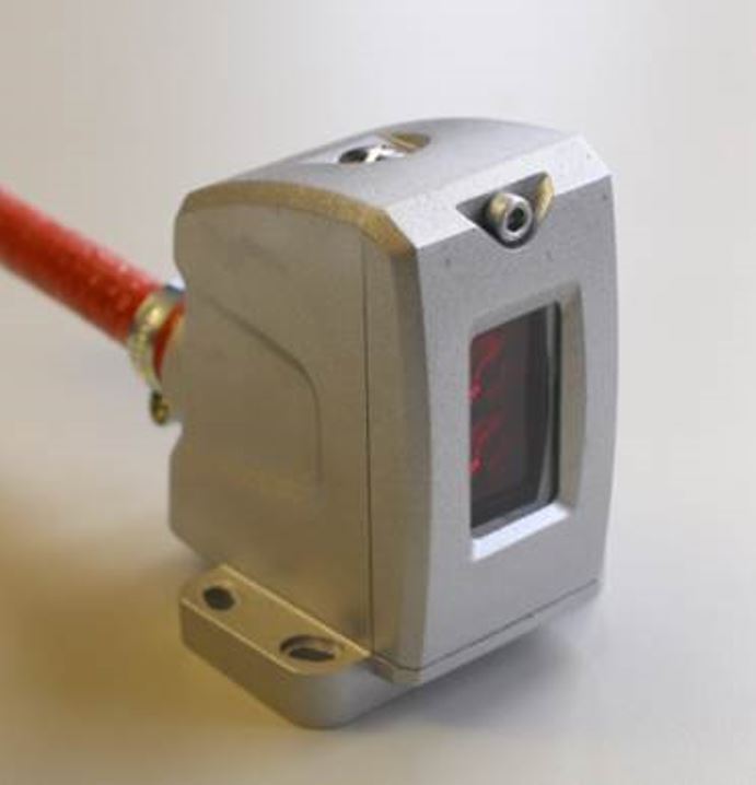
Add Protection
Sensor enclosure and protective cable sleeve
At many locations in the steel production process, the extensive heat is only temporary. In a hot rolling mill, a slab runs through a rougher mill multiple times before it continues to a multi-stage finishing mill stand to be rolled to the final thickness. After that the metal strip runs into the coiler to be winded up.
This process runs in sequence, and the glowing material is only present at each stage of production for a short time. Until a new slab runs out of the reheating furnace, temperatures normalize.
Standard sensors can work in these conditions, but you do run the risk of even temporary temperature hikes causing sensor failure and then dreaded downtime. To protect photoelectric sensors against temporary overheating, you can use a protective enclosure. These can provide mechanical and thermal protection to the sensors which often have plastic bodies. Additional protection can be achieved when a heat resistant sleeve is used around the cable.
Photoelectric sensors do have their limits and are not suitable for all applications, even when precautions are taken. Ask yourself these questions when deciding if they can be the right solution for your high temperature applications.
Which distance between the hot object and sensor can be realized?
What is the maximum temperature at this location?
How long will the sensor be exposed to the highest heat levels during normal operation and at breakdown?
In addition to distribution, we design and fabricate complete engineered systems, including hydraulic power units, electrical control panels, pneumatic panels & aluminum framing. Our advanced components and system solutions are found in a wide variety of industrial applications such as wind energy, solar energy, process control and more.
In press shops or stamping plants, downtime can easily cost thousands of dollars in productivity. This is especially true in the progressive stamping process where the cost of downtime is a lot higher as the entire automated stamping line is brought to a halt.
Many strides have been made in modern stamping plants over the years to improve productivity and reduce the downtime. This has been led by implementing lean philosophies and adding error proofing systems to the processes. In-die-sensing is a great example, where a few inductive or photo-eye sensors are added to the die or mold to ensure parts are seated well and that the right die is in the right place and in the right press. In-die sensing almost eliminated common mistakes that caused die or mold damages or press damages by stamping on multiple parts or wrong parts.
In almost all of these cases, when the die or mold is replaced, the operator must connect the on-board sensors, typically with a multi-pin Harting connector or something similar to have the quick-connect ability. Unfortunately, often when the die or mold is pulled out of the press, operators forget to disconnect the connector. The shear force excreted by the movement of removing the die rips off the connector housing. This leads to an unplanned downtime and could take roughly 3-5 hours to get back to running the system.
Another challenge with the multi-conductor connectors is that over-time, due to repeated changeouts, the pins in the connectors may break causing intermittent false trips or wrong die identification. This can lead to serious damages to the system.
Both challenges can be solved easily with the use of a non-contact coupling solution. The non-contact coupling, also known as an inductive coupling solution, is where one side of the connectors called “Base” and the other side called “Remote” exchange power and signals across an air-gap. The technology has been around for a long time and has been applied in the industrial automation space for more than a decade primarily in tool changing applications or indexing tables as a replacement for slip-rings. For more information on inductive coupling here are a few blogs (1) Inductive Coupling – Simple Concept for Complex Automation Part 1, (2) Inductive Coupling – Simple Concept for Complex Automation Part 2
For press automation, the “Base” side can be affixed to the press and the “Remote” side can be mounted on a die or mold, in such a way that when the die is placed properly, the two sides of the coupler can be in the close proximity to each other (within 2-5mm). This solution can power the sensors in the die and can help transfer up to 12 signals. Or, with IO-Link based inductive coupling, more flexibility and smarts can be added to the die. We will discuss IO-Link based inductive coupling for press automation in an upcoming blog.
Some advantages of inductive coupling over the connectorized solution:
Since there are no pins or mechanical parts, inductive coupling is a practically maintenance-free solution
Additional LEDs on the couplers to indicate in-zone and power status help with quick troubleshooting, compared to figuring out which pins are bad or what is wrong with the sensors.
Inductive couplers are typically IP67 rated, so water ingress, dust, oil, or any other environmental factor does not affect the function of the couplers
Alignment of the couplers does not have to be perfect if the base and remote are in close proximity. If the press area experiences drastic changes in humidity or temperature, that would not affect the couplers.
There are multiple form factors to fit the need of the application.
In short, press automation can gain a productivity boost, by simply changing out the connectors to non-contact ones.
In addition to distribution, we design and fabricate complete engineered systems, including hydraulic power units, electrical control panels, pneumatic panels & aluminum framing. Our advanced components and system solutions are found in a wide variety of industrial applications such as wind energy, solar energy, process control and more.
The complexity of factory automation creates constant challenges which drive innovation in the industry. One of these challenges involves the ability to accurately detect the presence of shiny or highly reflective objects. This is a common challenge faced in a variety of applications, from sensing wheels in an automotive facility to detecting an aluminum can for filling purposes at a beverage plant. However, thanks to advancements in photoelectric sensing technologies, there is a reliable solution for those type of applications.
Why are highly reflective objects a challenge?
Light reflects from these types of objects in different directions, and with minimum energy loss. This can cause the receiver of a photoelectric sensor to be unable to differentiate between a signal received from the emitter or a signal received from a shiny object. In the case of a diffuse sensor, there is also the possibility that when trying to detect a shiny object, the light will reflect away from the receiver causing the sensor to ignore the target.
So how do we control the direction of the light going back to the receiver, and avoid false triggering from other light sources? The answer is in polarized retroreflective sensors.
Retroreflective sensors require a reflector which reflects the light back to the sensor allowing it to be captured by the receiver. This is achieved by incorporating sets of three mirrors oriented at right angles from each other (referred to as corner cubes). A light beam entering this system is reflected by all three surfaces and exits parallel to the incident beam. Additionally, corner cubes are said to be optically active as they rotate the plane of oscillation of the light by 90 degrees. This concept, along with polarization, allow this type of sensor to accurately detect shiny objects.
Polarization
Light emitted by a regular light source oscillates in planes on dispersal axes. If the light meets a polarizing filter (fine line grid), only the light oscillating parallel to the grid is let through (see figure 1 below).
Figure 1
In polarized retroreflective sensors, a horizontal polarized filter is placed in front of the emitter and a vertical one in front of the receiver. By doing this, the transmitted light oscillates horizontally until it hits the reflector. The corner cubes of the reflector would then rotate the polarization direction by 90 degrees and reflect the light back to the sensor. This way, the returning light can pass through the vertical polarized filter on the receiver as shown below.
Figure 2
With the use of polarization and corner cubed reflectors, retroreflective sensors can create a closed light circuit which ensures that light detected by the receiver was sourced exclusively by the emitter. This creates a great solution for applications where highly reflective targets are influencing the accuracy of sensors or causing them to malfunction. By ensuring proper operation of photoelectric sensors, unplanned downtime can be avoided, and overall process efficiency can be improved.
In addition to distribution, we design and fabricate complete engineered systems, including hydraulic power units, electrical control panels, pneumatic panels & aluminum framing. Our advanced components and system solutions are found in a wide variety of industrial applications such as wind energy, solar energy, process control and more.
Both washdown and hygienic design are common terms used in the food and beverage industry, and are increasingly being used in the packaging industry. These terms are used in different scenarios and easily confused with each other. What exactly are the differences between them, and in what applications are each used?
Why are hygienic design and washdown needed?
The consumer, and more specifically, the health of the consumer is the core concern of the food and beverage industry. Contaminated food can pose a danger to life and limb. A product recall damages the image of a company, costs a lot of money and as a worst case scenario can lead to the complete closing of the company. To prevent such scenarios, a producers primary objective is to make sure that the food is safe and risk-free for the consumer.
In food manufacturing and packaging plants, a differentiation is made between the food area (in direct contact with the product), the spray area (product-related) and the non-food area. The requirements of the machine components are different depending on which area they are in.
The Food Area
In the food area the food is unpacked, or partially unpacked, and particularly susceptible to contamination. All components and parts that may come in contact with the food must not adversely affect this, e.g. in terms of taste and tolerability.
The following needs to be considered to avoid contamination:
Hygiene in production
Use of food contact materials
Food-grade equipment in Hygienic Design
These requirements result in the need for components that follow the hygienic design rules. If the component supplier fulfills these rules, the machine manufacturer can use the components and the producer can use the machines without hesitation.
Hygienic Design
Many component suppliers offer different solutions for hygienic design and each supplier interprets the design differently. So what does hygienic design mean? What must be included and which certifications are the right ones?
The material used must be FoodContact Material (FCM). This means that the material is non-corrosive, non-absorbent and non-contaminating, disinfectable, pasteurisable and sterilizable.
Seals must be present to prevent the ingress of microorganisms.
The risk of part loss must be minimized.
Smooth surfaces with a radius of < 0.8 μm are permitted.
There must be no defects, folds, breaks, cracks, crevices, injection-molded seams, or joints, even with material transitions.
There must be no holes or depressions and no corners of 90°.
The minimum radius should be 3 mm.
Supporting institutions and related certifications
There are different institutions which confirm and verify the fulfillment of these rules. They also support the companies during the development process. EHEDG – The European Hygienic Engineering and Design Group offers machine builders and component suppliers the possibility to evaluate and certify their products according to Hygienic Design requirements. 3A – 3-A Sanitary Standards, Inc. (3-A SSI) is an independent, non-profit corporation in the U.S. for the purpose of improving hygiene design in the food, beverage and pharmaceutical industries. The 3-A guidelines are intended for the design, manufacture and cleaning of the daily food accessories used in handling, manufacturing and packaging of edible products with high hygiene requirements. FDA – The Food and Drug Administration is a federal agency of the United States Department of Health and Human Services, one of the United States federal executive departments. Among other things, the FDA is responsible for food safety.
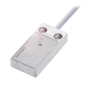
What does a hygienic design product look like?
Below is an example of a hygienic design product.
Stainless steel housing VA 1.4404
Laser marking
Protection class IP69K (IEC 60529)
Active surface made of PEEK
EHEDG conform
FDA conform
Since the product contacting area is associated with high costs for the plant manufacturer and the operator, it’s beneficial to keep it as small as possible.
The Spray Area
In the spray area, there are different requirements than in the food area.
Depending on the type of food that is processed, a further distinction is made between dry and wet areas.
Areas in the food and beverage production
Here we are talking about the washdown area. Washdown capable areas are designed for the special environmental conditions and the corresponding cleaning processes.
Washdown
Components which fulfill washdown requirements usually have the following features:
Cleaning agent/corrosion resistant materials (often even food compliant, but this is not a must)
High protection class (usually IP 67 and IP 69K)
Resistant to cleaning agents
Photoelectric sensor for washdown requirements
Ecolab and Diversey are two well-known companies whose cleaning agents are used for appropriate tests: Ecolab Inc. and Diversey Inc. are US based manufacturers of cleaning agents for the food and beverage industry. Both companies offer certification of equipment’s resistance to cleaning agents. These certificates are not prescribed by law and are frequently used in the segments as proof of stability.
The washdown component must also be easy and safe to clean. However, unlike the hygienic design, fixing holes, edges and threads are permitted here.
For basic information on IP69K see also this previous blog post.
To learn more about solutions for washdown and hygienic design click here.
In addition to distribution, we design and fabricate complete engineered systems, including hydraulic power units, electrical control panels, pneumatic panels & aluminum framing. Our advanced components and system solutions are found in a wide variety of industrial applications such as wind energy, solar energy, process control and more.
It is not a surprise that optimizing yield is one of the most important objectives in a sawmill (or lumber mill) as it is in any other industry. The big difference is that there is hardly any control over the quality of the logs that enter the sawill. In the ideal world all logs are not only cylindrical in shape but also straight. But obviously each individual log is unique in shape. Crooked, out-of-round, or tapered logs are common and even worse: usually it is a combination of these shapes.
Still the target is to recover as much yield from each log as possible. Therefore sawmills turn into highly automated factories with three dimensional (3D) measurement of logs, and advanced equipment for primary and secondary breakdown. Basically there are three areas of automation in a sawmill:
3D measurement for optimum cutting pattern to recover most yield from a log
Automation of drives to position the log itself, or tools (e.g. sawblades, knifes, canter heads…) at high velocity to increase throughput
Automation of log and lumber handling to minimize the gap between the logs
All of the three areas support the sawmill’s target to get the most out of the logs at the highest speed. The worst case is any downtime as it directly impacts the whole log to lumber process. Therefore electrical engineers look for sensors that meet the challenges of the sawmill environment. Mainly sensors must meet high vibration and shock standards. As they are exposed to the environment, protective housings help to protect the sensors from logs crashing into them.
From logs to lumber
Wave feeder with analog distance sensor
To efficiently process logs to lumber, sawmills use dedicated equipment for different sizes of logs. As a result bigger mills have a primary and a secondary breakdown area. Independent from the logs, sawmills aim to minimize the gaps and to avoid changes in the setup. This allows them to run faster and to increase the production rate. Here is the process how a log turns into lumber in a sawmill.
When a log arrives at the mill it is indexed onto the infeed conveyer (could be a step feeder or log loader). Either inductive sensors sequence the steps. Or a magnetostrictive position sensor (linear transducer) provides feedback of the step position of the loader to control motion and speed. Once the log is on the loader analog distance sensors determine the distance to the end of the log from the side of the loader wall.
This is to ensure a constant distance between the logs (log gap) as they enter the sawmill. Knowing the distance enables them to control when the log is loaded on the conveyor. And thereby they can control the gap. As an alternative photoelectric a thru beam sensor determines if a log is present for the final two steps on a loader. These sensors work with a long measuring range. Additionally they have a large functional reserve and are very resistant to dirt and dust.
Primary breakdown – from raw log to slabs and cants
The first step of the log is to run through a debarker that removes the bark. As there are tolerances in shape, linear transducers and photoelectric analog distance sensors are used to determine log sizes. These sizes help to adjust the debarker’s pressure and speed. After debarking the logs are cut to the best pre-determined length by cut-off or bucking saws. Again linear transducers are used to control the motion of the cut-off saw swing.
By stacking some photoelectric through beam sensors they can be used to determine the log diameter roughly. This leads to increasing speed as the saw can cut through smaller logs faster and has to slow down for larger logs. Many mills just sort their debarked logs into “large logs” and “small logs” based on their diameters. And then go into machines that are set up for those particular log sizes.
Log carriage for 20″ (50cm) logs and more
Carriage saw with BTL for positioning
Many mills also run a lot of larger logs and therefore have a log carriage. This is a single band saw with a carriage that runs on railway style tracks. The carriage has three or four knees that have positioners and log clamps (dogs) that hold the log. In the knees hydraulic cylinders with magnetostrictive transducers position the log. Even under extreme surrounding conditions, these position sensors guarantee a high machine and system availability. The clamps hold the log while it movesthrough the band saw. The carriage cuts the logs into slabs (two flat, two rounded sides) or into cants (four flat, square sides).
Secondary Breakdown – from small logs, slabs and cants to lumber
Mills that run smaller logs do not have to break down the logs prior to putting them through the secondary breakdown equipment. After the cut-off saw, the small logs will be sorted by size into bins. Step feeders index them again onto a conveyor and that feeds them through a Scanner into the small log line machine. To recover as much yield as possible log turners turn the logs in the optimum position. Chipper canters center them to enable curve sawing, which leads to increased lumber recovery.
Hydraulic drives dominate small log lines and all motion control happens with linear position transducers. Typical small log lines consist of log turning and centering, chipping with canter heads, saw box slew and skew, saw box positioniers, profiling heads and outfeed pickers. All of the equipments’ design aims for speed and therefore they require fast and accurate position feedback. Sensors and transducers must withstand high shock and vibration. Balluff’s products survive even in toughtest environments and undergo intensive shock and vibration testing.
Shifting edgers and curve sawing
Sawblade Adjustment with BTL
Gang edgers and shifting edgers cut cants and slabs from the primary breakdown into boards. Gang edgers have circular saws stacked at fixed spacing. Shifting edgers look similar to gang edgers except that they change spacing between saw blades can be changed. Therefore each saw is connected to a hydraulic positioner. A scanner looks at the cant or slab and determines the best solutions of cuts to produce best results. After the scanner the positioners of the shifting edgers set the new saw spacing to match that solution.
Edger optimizers pre-position the board and optimize the infeed to get the best payback from the machine. Photoelectric (laser) retroreflective sensors track boards through the ducker table. The infeed position cylinder (with integrated linear transducer) skews the board in the best position to be fed in the edger.
Trimming, sorting, stacking, strapping, shipping
Photoelectric sensors detect boards at the trimmer infeed
The boards go into bins when they come out of the edgers. Another scanner determines if the board can be cut down into shorter boards. Or if a damaged end needs to be cut off so that the board is not graded lower. The next step is processing the board through a trimmer. The trimmer is a set of up to about a dozen circular saws positioned across the conveyor. It can cut longer boards down into two or three shorter boards or just trim the ends.
Photoelectric analog distance sensors detect stacked boards from high distance
Background suppression photoelectric sensors at the indeed of the trimmer look down at the board as it goes into the machine. And they determine if the board is actually as long as the scanner information indicates. The same sensors confirm after the trimmer that the board was cut down to the proper size. After the trimmer they go into a sorter and and from there to stacking and strapping to final shipment.
We provide additional information how our sensors help to automate sawmills on our website.
Veneer instead of solid wood
A sawmill produces solid wood. This means that the board is out of one piece of wood. Another type of boards is veneer. This means that thin layers of wood are glued together to reach a board. Usually these layers are less that 3 mm thick. A lathe continuously turns a log against a blade to peel it. With each rotation the log becomes thinner. Therefore the blade position needs to be adjusted. Hydraulic cylinders with integrated linear transducers centerthe log and position the blade to peel the trunk. The thin layers are glued together in a veneer press.
Not only stationary, but also portable sawmills
In the end our sensors and transducers not only help to automate huge mills, but also portable sawmills. Magnetostrictive or magnetically sensors enable operators to exactly position the saw unit. So they achieve accurate and fast cutting of boards. Wood-Mizer is a world leading supplier of efficient and fast portable sawmills that uses magnetostrive position sensors in it’s machines. The reasons for Balluff are its product and service quality as well as the availability.
In addition to distribution, we design and fabricate complete engineered systems, including hydraulic power units, electrical control panels, pneumatic panels & aluminum framing. Our advanced components and system solutions are found in a wide variety of industrial applications such as wind energy, solar energy, process control and more.


 It is not a surprise that optimizing yield is one of the most important objectives in a sawmill (or


