
Efficient and cost-saving – the IO-Link advantage
The IO-Link communication interface offers tangible benefits: quick and cost-saving installation, continuous diagnostics and quick sensor replacement, because these can be configured from a central location. All in all, this provides more flexibility and increases the efficiency of automation.
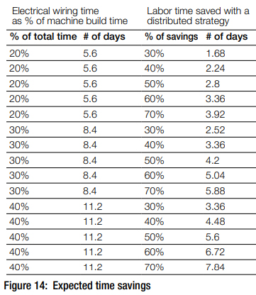
Easy installation
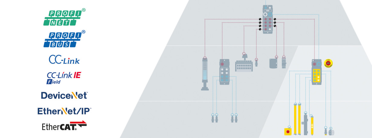
For IO-Link all you need is an industry-standard three- or four-conductor cable. The uniform standard interface can be quickly integrated into the fieldbus world. Even complex devices can be easily integrated. What is particularly interesting is that even without expensive, shielded cabling, the digital communication ensures noise immunity. Analog signals are digitized with no conversion losses.
IO-Link increases machine availability
IO-Link enables quick and error-free exchange of sensors and shortens the time needed to start system operation. Downtime can be significantly reduced, since the IO-Link master or the controller automatically writes the parameters of a replaced IO-Link sensor onto the new sensor. Commissioning processes, format changes or recipe changes are handled centrally via the controller’s function modules. This saves time and minimizes the potential for mistakes. Additional advantages for you: IO-Link devices cannot be confused with each other as they are automatically identifiable via IO-Link.
IO-Link enables need-oriented maintenance
Continuous diagnostic data for the entire process extends your service intervals, since automatic readjustment via IO-Link means you need to perform maintenance much less frequently on equipment and machines. Now, predictive error detection is even possible because complete process parameters are consistently displayed in the controller.
IO-Link makes operation more efficient
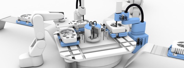
IO-Link sensors can be positioned in the machine directly at the location of operation because the sensor’s accessibility no longer plays a role. That is optimal in terms of technical aspects of the process. Process monitoring, configuration and error analysis of the IO-Link sensors take place in the controller. Machine processes are now time-optimized. Additionally, signal delays and distortions are reliably eliminated because the digital transmission of data also ensures high signal quality. A wide range of application requirements can be easily met with IO-Link due to standard binary and analog devices being used at the same time as IO-Link sensors and actuators.
IO-Link offers a high-performance, consistent network
Control concepts using IO-Link provide you with simple and universal solutions for a high-performance, consistent network, meaning you benefit from lower costs and are more flexibility than ever.
We Speak IO-Link
The advantages of IO-Link are obvious: easy installation, high machine availability, need-oriented maintenance, efficient operation and a high-performance, consistent network. As an engaged partner for industrial automation, Balluff offers not only an enormously wide spectrum of products and services with devices such as our IO-Link master, IO-Link hubs and IO-Link sensors, but together with you also develops solutions for industrial automation that are precisely suited to your needs and are globally applicable.
Examples
CMA/Flodyne/Hydradyne is an authorized Balluff distributor in Illinois, Wisconsin, Iowa and Northern Indiana.
In addition to distribution, we design and fabricate complete engineered systems, including hydraulic power units, electrical control panels, pneumatic panels & aluminum framing. Our advanced components and system solutions are found in a wide variety of industrial applications such as wind energy, solar energy, process control and more.


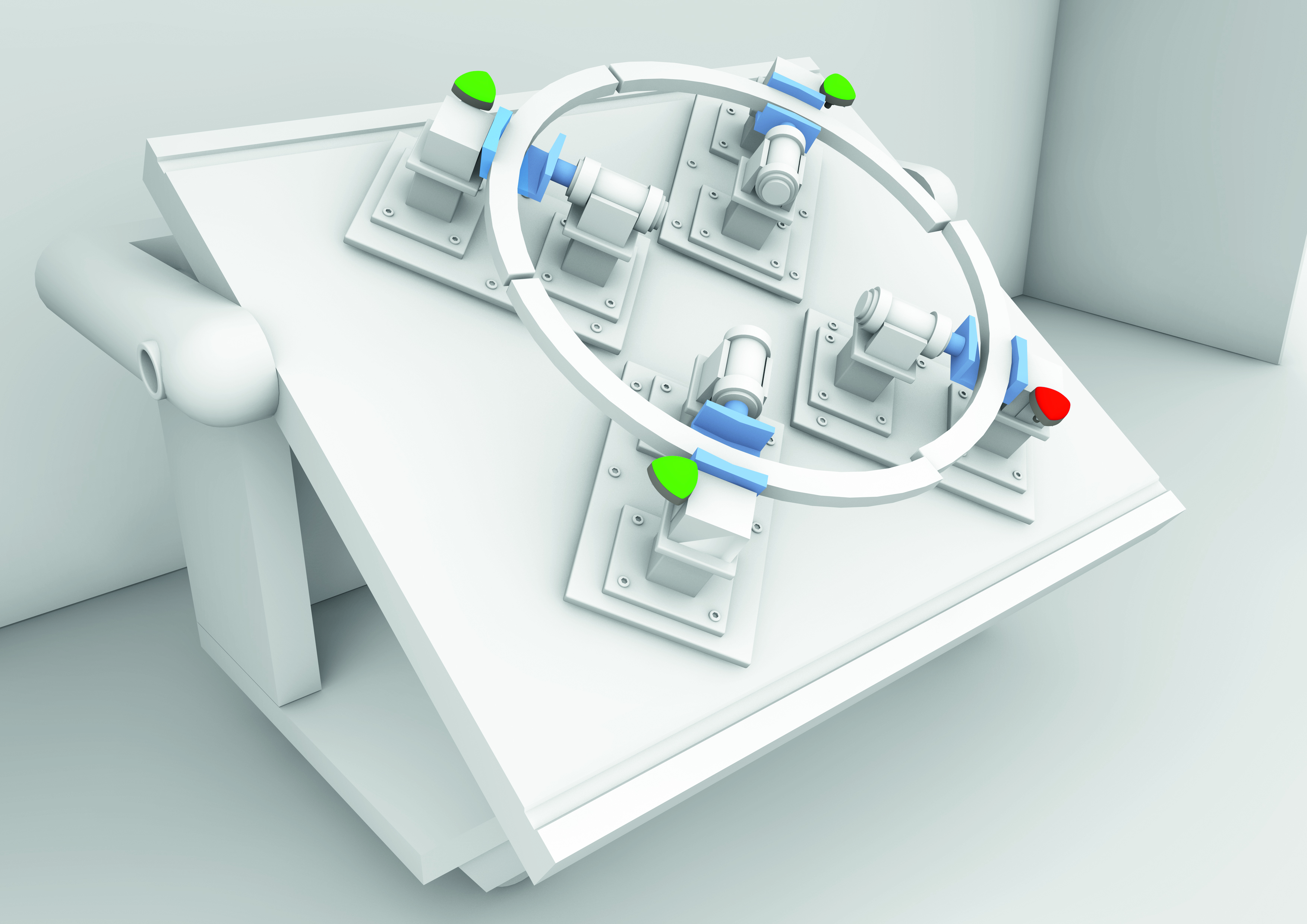 A manually-fed weld-cell with smart indicators is capable of not only signaling that the part is loaded correctly, but also if the part is out of alignment (shown by the red indicator) or that there is something wrong with one of the automation components such as a stuck pneumatic clamp.
 A traditional kitting station, sometimes referred to as a supermarket, with smart indicators to guide operators to the intended part to pull.