Guest contributor; Dr. Steffen Haack, Bosch Rexroth AG
When it comes to progress in linear motion technology, one thing is immediately clear: linear guides and systems move increasingly larger loads more regularly and with increasingly higher positioning accuracy and repeatability. Anyone with an understanding of the interplay between the drive technologies will know the potential resulting from it.
Through a combination of electrics, sensors and software, linear motion technology makes a crucial contribution for integrated factory. Here are the five trends that support intelligent linear motion technology in practice:
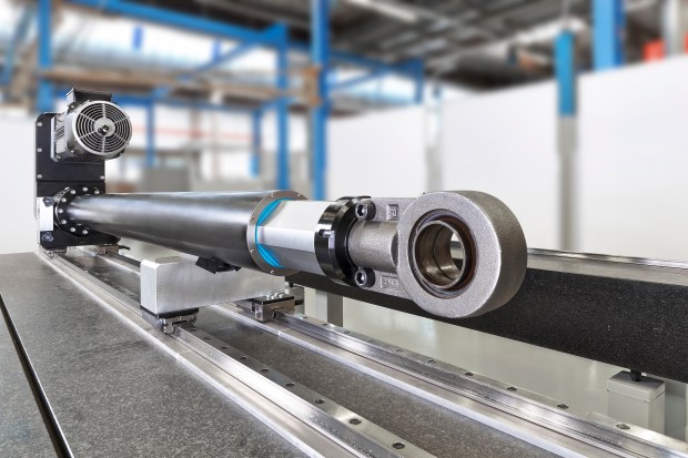
Figure 1: Modularization and flexibility
Ready-to-install electromechanical cylinders combine mechanics with the flexibility of electric drives. A software command to the electric drive and the cylinder move them to any position and carry out complicated movement profiles. Without an additional position measuring system, they can achieve repeatability of up to ± 0.01 mm. Load measuring pins transmit the values analogously to the electric drive or the control and enable a decentralized process management.
If the precision requirements are high but the environment conditions are rough, conventional measuring systems soon reach their limits. Absolute measuring systems integrated into ball rail and roller rail systems detect the absolute position of the axis with a resolution of 0.025 μm. They immediately recognize the absolute position of the axis when the machine is switched on and report it to the controller without carrying out a reference run. In addition, modern systems do not require buffer batteries that need to be replaced regularly.
Sensors measure temperature peaks and vibrations. This data forms the basis for future approaches to predictive maintenance. However, it is only significant if it is compared with life cycle models. In load tests, the newly developed runner blocks have demonstrated twice the service life through increased load capacities with the same size. Together with the detected operating conditions and predictive maintenance, they significantly increase the availability of machines and systems.
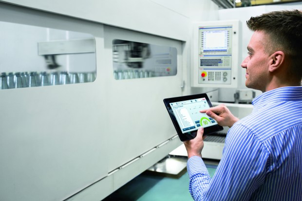
Figure 4: Digitally supported commissioning
Previously, an experienced technician could easily have spent twenty minutes commissioning a linear axis. With the new mechatronic linear axes and actuators, the commissioning takes only three to five minutes. A digital assistant supports the application engineer with this. The technician only has to enter a few pieces of axis-specific data and can then immediately program or parameterize the drive. In the future, this functionality will automatically be available via the QR code.
Figure 5: Digital engineering for secure and quick dimensioning
More and more engineering departments are changing to integrated digital workflows. With selection guides or sizing tools, design engineers find the correct linear motion technology components and mechatronic systems through intuitive user guidance, which can even be application-specifically configured. The electronically generated data are then integrated directly into the digital construction model and enables the virtual simulation of complex machine movements, for example.
Do you have questions about this post? Please contact us:
In addition to distribution, we design and fabricate complete engineered systems, including hydraulic power units, electrical control panels, pneumatic panels & aluminum framing. Our advanced components and system solutions are found in a wide variety of industrial applications such as wind energy, solar energy, process control and more.
Todd Sharp, Motion Control Sales Manager, CMA/Flodyne/Hydradyne
CMA/Flodyne/Hydradyne is a leader in the design and commission of drive and control
systems for our customers for over 30 years, and one question that we often hear is “Why is Rexroth the best?” There are many brands competing for the drive and control market, and here at CMAFH, we have working experience with most if not all of them. Our engineers program, repair and upgrade many of the brands of control systems, and we have the ability to integrate any brand into our custom projects at our customer’s request. Having specialized in Bosch Rexroth products for many years, we understand the unique strengths of the product line.
Rexroth drives and controls can be differentiated from competing brands in four very distinct ways.
1. Product Breadth
The IndraDrive product family spans the power range from 100W to 4MW. This product family can operate as an open loop frequency drive/sensor less vector drive up to a multi-axis integrated motion and logic controller that can be either stand alone or drive resident. The IndraDrive product family also includes a cabinet free drive integrated motor. This entire IndraDrive product family is supported by the same software.
Power range from 100W to 4MW
Range of technology from open loop V/F and sensor-less vector control to multi-axis integrated motion and logic control
Integrated motion and logic control – controller or drive resident
Cabinet free drive integrated motor
2. Connectivity
Rexroth’s drive and control platform supports all common communication buses including Ethernet I/P, EtherCAT, Profinet, SERCOS, CANopen, Powerlink, Profibus.
We can control 3rd party motors regardless of brand or type, and we can operate all common feedback types including TTL, 1vpp, Endat, Hiperface, SSI, resolver. Our drives are available with a 2nd encoder input with a 1MHZ input frequency. Our control supports all common machine programming languages like ladder, FB, ST, IL… plus all common IT and engineering languages like C#, C++, Java, Labview, Matlab.
Supports all common communication buses including, Ethernet I/P, EtherCAT, ProfiNet, SERCOS, CANopen, Powerlink, Profibus
Controls all 3rd party motors regardless of brand or technology type
Operates all common feedback types (TTL, 1vpp, ENDAT, Hiperface, SSI, resolver) with drive based second encoder input with up to 1MHZ input frequency
Supports all common machine programming languages (ladder, FB, structured text, instruction list) plus all common IT and engineering type languages like C#, C++, Java, Labview, Matlab
3. Functionality
Whether it’s drive or controller based, Rexroth offers multi-zone tension control, vibration dampening/anti-slosh control, high speed registration control, advanced electronic camming and hydraulic control. We also support zoned safety control with safe torque off and full safe motion; controller or drive based. Yes, drive based safe motion control!
Multi -zone tension control
Vibration dampening/anti-slosh control
High speed registration control
Advanced electronic camming
Supports all common hydraulic functions
Integrated safe torque off and safe motion control
4. Support
Rexroth designs, engineers and manufactures all products they sell. All are standard and sold throughout the world. In the US, hundreds of local high-tech distributors are Rexroth trained and certified to provide full sales, service and application support. Additionally, Rexroth maintains sales, service and application support facilities in every region of the US, plus scores more globally.
All products are standard and sold throughout the world
Bosch Rexroth maintains sales, service and application support facilities in every region of the US and scores more globally
In the US hundreds of local high-tech distributors are Rexroth trained and certified to provide additional sales, service and application support
Do you have questions about this post? Please contact us:
In addition to distribution, we design and fabricate complete engineered systems, including hydraulic power units, electrical control panels, pneumatic panels & aluminum framing. Our advanced components and system solutions are found in a wide variety of industrial applications such as wind energy, solar energy, process control and more.
Guest contributor: Richard Meyerhoefer, Delta Computer Systems
Fastener stamping machine output triples after tuning the motion with a solution from Delta Computer Systems.
Improving the productivity of a manufacturing process by speeding up the operation of an old machine can be very difficult, driving plant managers to purchase new equipment. It’s often possible, however, to replace the control system, maintaining the old mechanics, and get the performance of a new machine for much lower cost. Hydraulics distributor CMA/Flodyne/Hydradyne (CMAFH) of Hanover Park, Illinois, recently assisted in such an upgrade for a manufacturer of fastening components. The machine was a press used to imprint patterns on the surface of metal fasteners with a punch that fits into the bottom of a 4″ bore hydraulic cylinder (Figure 1). As the punch comes down it reshapes the top of the fastener and its edges to provide a locking feature.
Motion controller selection
Figure 1. Diagram showing motion controller connections in the fastener press machine
In the past, the manufacturer used a programmable logic controller (PLC) to operate a two-position, bang-bang valve to drive the cylinder, but company engineers found imprecise results that limited production to around 60-to-70 parts per minute. As a result, the company moved to a proportional valve and closed-loop controller that operated the valve based on cylinder position/acceleration. The controller would open the valve quickly and then back off the valve as the cylinder got closer to making contact with the fastener. This method enabled an increase in production to approximately 140 parts per minute. But to meet competitive pressures, company managers demanded the rate be increased, driving the need for a new electro-hydraulic motion controller.
Company engineers called CMAFH, with whom they had worked on automation solutions for more than 20 years, to recommend a new controller for the company’s old bang-bang machine.
Hooking up the controller
The Delta RMC75E motion controller (Figure 2), recommended by CMAFH engineering manager Norman Dziedzic, accurately controls position and force, to control acceleration with more precision than the closed-loop controller previously used. Dziedzic programmed the motion controller to move the cylinder to a predetermined position while monitoring the force being applied by the punch. When the force reaches a particular value, the controller is switched to force control mode to ensure that adequate force is ultimately applied to the fastener. The old closed-loop control system used position control only, with some input from a load cell within the tool to verify that a certain minimum force was applied to the part.
“The Delta controller operates similar to that, but is easier to control,” says Richard Mellor, engineer at the fastener company. Every motion step made by the other controller was initiated by the PLC, and there was lag time in passing position information. “The beauty of the Delta controller is that the motion program now resides in the controller,” Mellor adds.
Now, the PLC just does overall machine control, triggering the Delta RMC to press the part at the appropriate time. When the pressing operation is complete, the Delta controller knows, based on the position and force ranges inputted to the controller, whether the pressed part is a good part or a bad one, and notifies the PLC. The Delta RMC75E gets cylinder position feedback from a linear magnetostrictive displacement transducer (LMDT) via a synchronous serial interface (SSI) to the controller. To measure force, the system uses a fatigue-rated (rugged) force transducer (shown in Figure 1).
Programming, tuning
Figure 2. The Delta RMC75E motion controller can control up to two motion axes simultaneously
Dziedzic set up the motion program initially, and he fine-tuned the loop parameters working with a fastener company engineer. The two also developed the code to implement quality testing of the finished parts.
“I find the Delta very easy to program, but I have 30 years in as a controls engineer. If you’ve had anything to do with PLC or message display packages, it’s relatively intuitive to find your way around,” Mellor says
For tuning the motion, Dziedzic relied heavily on Delta Computer Systems’ Plot Manager software, which allows an engineer to view multiple key motion parameters versus time on a single graph (Figure 3). The plot shows three press cycles, where the red curve is the actual position of the press cylinder, the blue curve is the actual velocity of the cylinder, and the force being applied by the die to the work piece is shown by the black line. The cyan line is the target cylinder position. When the motion system is perfectly tuned, the actual cylinder position curve overlaps the target position, indicating that any positioning error caused by the mechanical aspects of the system – for example, the compressibility of the fluid or the friction of the moving parts – has been compensated for by the control algorithm. In Figure 3, the flat yellow line indicates the command force which must be applied to the part to make the press operation successful. The circle marked A highlights the point in time when the actual position (red line) begins to deviate from the target position (cyan line) as the tool comes into contact with the part. This is also when the force (black line) begins to climb. Then, at point B, the change in actual velocity (blue curve) shows force control taking over from position control. Area C in the plot shows when the actual force meets the target command force to signal a successful operation. Area D shows harmless motion transients that are caused by retracting the cylinder quickly to prepare for pressing the next part.
Using the Plot Manager, motion characteristics that occur too quickly to be visible to the naked eye can be analyzed and corrected if necessary, enabling the manufacturing process to be accelerated.
Results
Figure 3. Delta’s RMCTools plot Manager software shows axis position and force versus time, enabling precise tuning of the motion.
One of the fastener company’s other key requirements on the controller upgrade project was to provide a means of accessing process data using the controller in order to do a pass/fail test on the finished parts.
“We track final position reached and maximum force achieved,” Dziedzic says. Previously, the company needed an external analog device to do this. Now, the Delta RMC75E eliminates this need by making process parameters available for the PLC to read directly over Ethernet. “The fact that the Delta controller can do this in addition to controlling the cylinder provides a huge benefit to them.”
“We have been very happy with the performance increase we have gotten with the Delta motion controller,” Mellor adds. “Even if we hadn’t gotten the performance, Delta’s ease of use in system setup and tuning would have made the difference.”
With the Delta RMC75E controlling the operation of the cylinder, the machine can now process up to 180 fasteners per minute.
“We can move faster because we have more control over the proportional valve, yielding tighter control loops and better control of the gain in the system,” Mellor says.
Another advantage of using the Delta RMC is operation repeatability; the controller is able to control the force exerted in each cycle to a tolerance of ±40 lb out of 10,000 lb applied.
In addition to distribution, we design and fabricate complete engineered systems, including hydraulic power units, electrical control panels, pneumatic panels & aluminum framing. Our advanced components and system solutions are found in a wide variety of industrial applications such as wind energy, solar energy, process control and more.
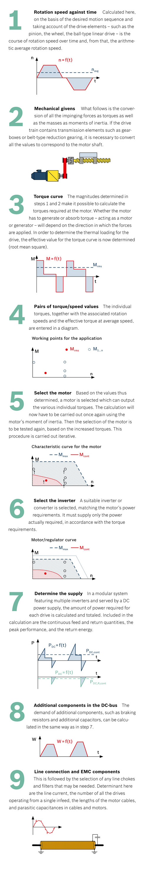
A fully structured approach, well-founded knowledge of the formulae and a fundamental understanding of the technology are essential to designing drives. These are the prerequisites for perfect matching of the machine and the drive.
Drive engineering is undertaken when the machine is initially designed, and also when the requirements for the machine have changed or a retrofit is due. Leaving excess tolerances – either upward or downward – is counterproductive for the design. If the drive is under-dimensioned, then the machine will not achieve the desired performance level and, in the worst case, the drive will have to be changed out for a more powerful one. That involves major outlays. The procurement costs will rise and because of poor efficiency, the life-cycle costs will increase. But what does designing a drive mean? It means laying out the motor’s torque curve so that it ideally matches the needs of the machine being served.
Technical understanding is a prerequisite
Software can provide assistance when calculating and planning the drive. It can save time, for example, when several versions have to be analyzed. With the help of the IndraSize engineering tool made by Rexroth, users can select IndraDyn motors and IndraDrive drives simply by entering parameters. But in spite of this support, the technician or engineer has to bring with him or her a fundamental understanding of the technology involved. Technical understanding will allow critical magnitudes to be taken into account so that we will recognize how the drive might be optimized. Whether with software support or without – the calculations for the proper drive can be carried out in nine clear steps.


 Powerlink, Profibus
 Multi -zone tension control