IO-Link

4 Reasons Why Machine Builders Use IO-Link

Corey Shepherd, CMAFH Brain Products Team

So, why might a machine builder use IO-Link? Here are a few reasons:

1.      Flexibility

IO-Link provides a flexible and easy-to-use interface that allows for the seamless integration of sensors and actuators from different manufacturers. This makes it easier to customize and upgrade automation systems as needed.

Machine builders can use IO-Link to connect a wide range of sensors and actuators, such as pressure sensors, temperature sensors, flow meters, solenoid valves, and even motors.

2.      Cost savings

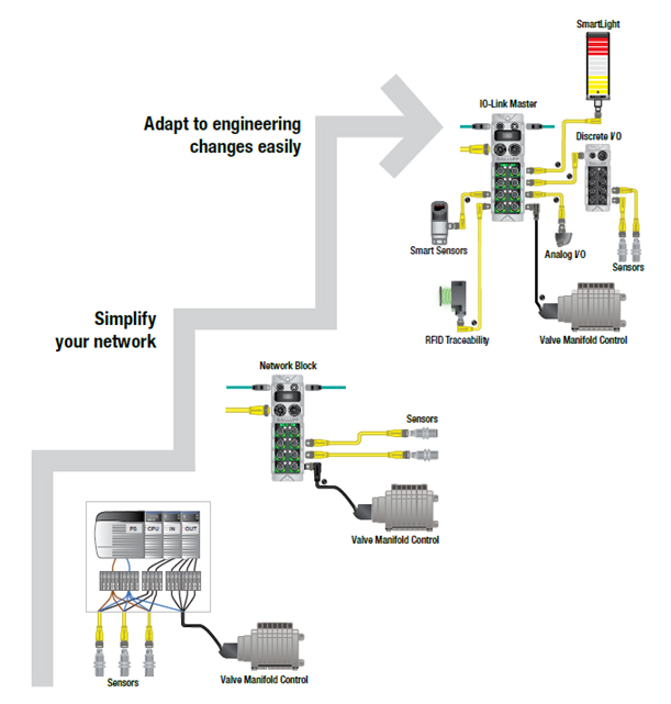
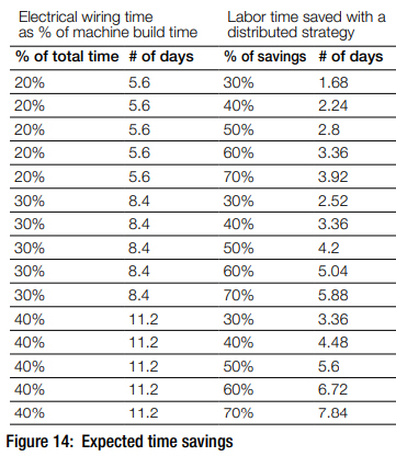
IO-Link can help reduce installation and maintenance costs by simplifying wiring and reducing the need for specialized cabling.

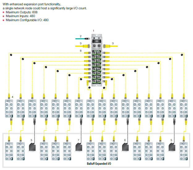
With IO-Link, machine builders can use standard unshielded three-conductor cables for all connections, reducing the number of cables required and simplifying the wiring process. Instead of individually wiring devices back to a terminal strip or IO modules, IO Link allows machine builders to land devices to IP67 or IP69K machine mount M12 IO Link masters or hubs.  

3.      Increased functionality

Additionally, IO-Link sensors and actuators can provide diagnostic information that can help reduce downtime and increase overall system efficiency.

IO-Link can provide advanced features such as parameterization, identification, and diagnostic capabilities. With parameterization, machine builders can configure and adjust sensor and actuator settings, such as sensing range and output type, to meet specific application requirements. Identification enables automatic identification and configuration of IO-Link devices when they are connected to the system. And with diagnostic capabilities, machine builders can monitor and diagnose issues with sensors and actuators in real-time, helping to reduce downtime and increase system efficiency.

4.      Simplifying Safety

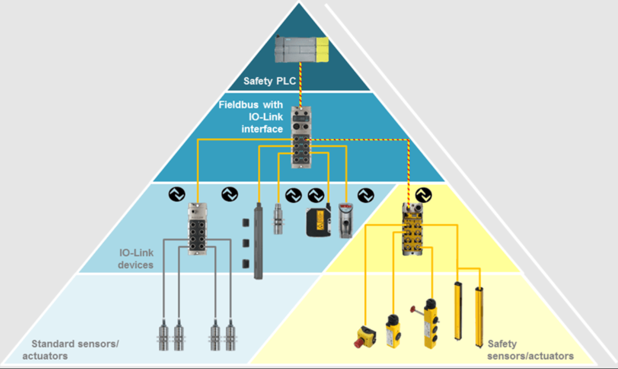
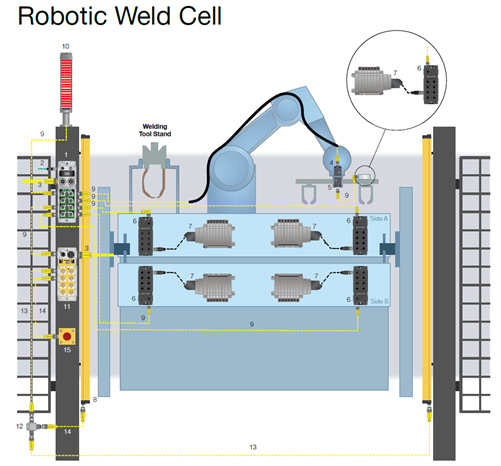
It is also possible to integrate safety devices with a PLE/SIL 3 rating in to your IO Link system if the correct hardware is used. Safety IO Link enables communication between safety devices, such as light curtains, E-Stop buttons, safety door switches, and a safety PLC.

Safety IO Link allows for more effective monitoring and control in industrial applications because each safety device can communicate its status and diagnostic information to the safety controller. This allows for simple and quick identification of safety fault issues. This is all accomplished with quick M12 connections between safety devices and a Safety IO Link module.

About Us

CMA/Flodyne/Hydradyne is a leader in the IO Link space by helping customers with full machine layouts using Balluff IO Link Masters, hubs, and devices. We would love an opportunity to show you how we can help optimize the right IO Link system for your machine!

Corey Shepherd.
CMA/Flodyne/Hydradyne Brain Products Team

Contact me at:
Office: 630-563-3710
Mobile: 847-899-2390
email: coreyshepherd@cmafh.com

cmafh.com

Building Blocks of the Smart Factory Now More Economical, Accessible

Guest Contributor: Balluff

A smart factory is one of the essential components in Industry 4.0. Data visibility is a critical component to ultimately achieve real-time production visualization within a smart factory. With the advent of IIoT and big-data technologies, manufacturers are finally gaining the same real-time visibility into their enterprise performance that corporate functions like finance and sales have enjoyed for years.

The ultimate feature-rich smart factory can be defined as a flexible system that self-optimizes its performance over a network and self-adapts to learn and react to new conditions in real-time. This seems like a farfetched goal, but we already have the technology and knowhow from advances developed in different fields of computer science such as machine learning and artificial intelligence. These technologies are already successfully being used in other industries like self-driving cars or cryptocurrencies.

1
Fig: Smart factory characteristics (Source: Deloitte University Press)

Until recently, the implementation or even the idea of a smart factory was elusive due to the prohibitive costs of computing and storage. Today, advancements in the fields of machine learning and AI and easy accessibility to cloud solutions for analytics, such as IBM Watson or similar companies, has made getting started in this field relatively easy.

One of the significant contributors in smart factory data visualization has been the growing number of IO-Link sensors in the market. These sensors not only produce the standard sensor data but also provide a wealth of diagnostic data and monitoring while being sold at a similar price point as non-IO-Link sensors. The data produced can be fed into these smart factory systems for condition monitoring and preventive maintenance. As they begin to produce self-monitoring data, they become the lifeblood of the smart factory.

Components

The tools that have been used in the IT industry for decades for visualizing and monitoring server load and performance can be easily integrated into the existing plant floor to get seamless data visibility and dashboards. There are two significant components of this system: Edge gateway and Applications.

2
Fig: An IIoT system

Edge Gateway

The edge gateway is the middleware that connects the operation technology and Information technology. It can be a piece of software or hardware and software solutions that act as a universal protocol translator.

As shown in the figure, the edge gateway can be as simple as something that dumps the data in a database or connects to cloud providers for analytics or third-party solutions.

Applications

One of the most popular stacks is Influxdb to store the data, Telegraf as the collector, and Grafana as a frontend dashboard.

These tools are open source and give customers the opportunity to dive into the IIoT and get data visibility without prohibitive costs. These can be easily deployed into a small local PC in the network with minimal investment.

The applications discussed in the post:

Grafana

Telegraf

Influxdb

Node-red Tutorial

CMA/Flodyne/Hydradyne is an authorized  Balluff distributor in Illinois, Wisconsin, Iowa and Northern Indiana.

In addition to distribution, we design and fabricate complete engineered systems, including hydraulic power units, electrical control panels, pneumatic panels & aluminum framing. Our advanced components and system solutions are found in a wide variety of industrial applications such as wind energy, solar energy, process control and more.


How Cameras Keep Tire Manufacturers From Spinning Their Wheels

Guest contributor: John Tackacs, BalluffTires being transported between the curing presses and the staging area before their final inspection often become clustered together. This jam up can cause imperfections to the tires and damage to the conveyors. To alleviate this problem, some tire manufacturers have installed vision systems on their conveyors to provide visual feedback to their production and quality teams, and alert them when the tires start to get too close together.

A vision system can show you alerts back in your HMI by using inputs and outputs built into the camera or use an IO-Link port on the camera to attach a visual display, for example a SmartLight with audible and flashing alerts enabled. Once you see these alerts, the PLC can easily fix the issue from the program or a maintenance worker or engineer can quickly respond to the alert.

Widespread use of smart vision cameras with various pixel options has become a trend in tire manufacturing. In additional to giving an early alert to bunching problems, vision systems can also capture pictures and data to verify that tires were cleared all the way into final inspection. Although tire machine builders are being asked to incorporate vision systems into their machines during the integration process, it is more likely for systems to be added in plants at the application level.

Vision systems can improve production throughput, quality issues and record production data about the process for analytics and analysis down the road. Remember a tire plant usually consists of these processes in their own large section of the plant and involves many machines in each section:

  • Mixing
  • Tire Prep
  • Tire Build
  • Curing
  • Final Inspection

Each one of these process areas in a plant can benefit from the addition of vision systems. Here are a few examples:

  • Mixing areas can use cameras as they mill rubber and detect when rubber sheets are off the rollers and to look for engraved information embedded in the rubber material for logistics and material flow to the proper processes.
  • Tire Prep can use cameras to ensure all the different strand colors of steel cords are embedded or painted on the rubber plies before going to tire build process.
  • Tire Build can use vision to detect the side-wall beads are facing the right direction and reading the embedded position arrows on the beads before tire plies are wrapped around them.
  • Curing area can use vision to monitor tire clusters on conveyors and make sure they are not too close to each other by using the measuring tool in the camera software.
  • Final Inspection can use vision to read barcodes, QR codes, detect colors of embossed or engraved serial numbers, detect different color markings and shape of the markings on the tire.

The use of machine vision systems can decrease quality issues by pinpointing errors before they make it through the entire production process without detection.

cropped-cmafh-logo-with-tagline-caps.png

CMA/Flodyne/Hydradyne is an authorized  Balluff distributor in Illinois, Wisconsin, Iowa and Northern Indiana.

In addition to distribution, we design and fabricate complete engineered systems, including hydraulic power units, electrical control panels, pneumatic panels & aluminum framing. Our advanced components and system solutions are found in a wide variety of industrial applications such as wind energy, solar energy, process control and more.

Adding a higher level of visibility to older automation machines

It’s never too late to add more visibility to an automation machine.

In the past, when it came to IO-Link opportunities, if the PLC on the machine was a SLC 500, a PLC-5, or worse yet, a controller older than I, there wasn’t much to talk about. In most of these cases, the PLC could not handle another network communication card, or the PLC memory was maxed, or it used a older network like DeviceNet, Profibus or ASi that was maxed. Or it was just so worn out that it was already being held together with hope and prayer. But, today we can utilize IIoT and Industry 4.0 concepts to add more visibility to older machines.

IIOT and Industry 4.0 have created a volume of products that can be utilized locally at a machine, rather than the typical image of Big Data. There are three main features we can utilize to add a level of visibility: Devices to generate data, low cost controllers to collect and analyze the data, and visualization of the data.

Data Generating Devices

In today’s world, we have many devices that can generate data outside of direct communication to the PLC.  For example, in an Ethernet/IP environment, we can put intelligent devices directly on the EtherNet/IP network, or we can add devices indirectly by using technologies like IO-Link, which can be more cost effective and provide the same level of data. These devices can add monitoring of temperature, flow, pressure, and positioning data that can reduce downtime and scrap. With these devices connected to an Ethernet-based protocol, data can be extracted from them without the old PLC’s involvement.  Utilizing JSON, OPC UA, MQTT, UDP and TCP/IP, the data can be made available to a secondary controller.

Linux-Based Controllers

An inexpensive Raspberry Pi could be used as the secondary controller, but Linux-based open controllers with industrial specifications for temperature, vibration, etc. are available on the market. These lower cost controllers can then be utilized to collect and analyze the data on the Ethernet protocol. With a Linux based “sandbox” system, many programming software packages could be loaded, i.e. Node-Red, Codesys, Python, etc., to create the needed logic.

Visualization of Data

Now that the data is being produced, collected and analyzed, the next step is to view the information to add the extra layer of visibility to the process of an older machine. Some of the programming software that can be loaded into the Linux-based systems, which have a form a visualization, like a dashboard (Node-Red) or an HMI feel (Codesys). This can be displayed on a low-cost monitor on the floor near the machine.

By utilizing the products used in the “big” concepts of IIOT and Industry 4.0, you can add a layer of diagnostic visualization to older machines, that allows for easier maintenance, reduced scrap, and predictive maintenance.

cropped-cmafh-logo-with-tagline-caps.png

CMA/Flodyne/Hydradyne is an authorized  Balluff distributor in Illinois, Wisconsin, Iowa and Northern Indiana.

In addition to distribution, we design and fabricate complete engineered systems, including hydraulic power units, electrical control panels, pneumatic panels & aluminum framing. Our advanced components and system solutions are found in a wide variety of industrial applications such as wind energy, solar energy, process control and more.

5 HYDRAULICS MYTHS

Guest Contributor: Dr. Steffen Haack, Bosch Rexroth

br_hydrolicmyths_hero_dec19.jpgNo drive technology is more efficient, compact and robust than hydraulics when dealing with forces in excess of 600 kN. So why is it that the importance of hydraulics is often overlooked in the training and development of our young engineers?

In the modern manufacturing setting, movement is everything along with the resulting data. Little thought is given to hydraulic technology, that is until drive physics comes into play. This is when hydraulic technology comes into its own in managing large forces and delivering robust performance.

Here’s a connected hydraulics ‘Myth Buster’ that demonstrates how the latest smart hydraulics are more versatile and cost-effective than you ever imagined.

THE MYTH: Installation is complex

BUSTED: Designers are no longer required to develop an in-depth knowledge of fluid mechanics and technology and increasingly look for plug & produce modules. These ready-to-install modules simply need an electrical current and a connection to the control communication.

THE MYTH: Commissioning takes time

BUSTED: Our smart, connected hydraulics are now commissioned with the same engineering tools as electric drives and control systems. Functions previously carried out hydromechanically are handled by the latest drive software. There are even software assistants available to guide technicians through the commissioning process and suggest suitable parameters.

THE MYTH: Hydraulics waste energy

BUSTED: There’s a preconception that hydraulics are more energy-intensive than other technologies, but things have changed dramatically. Variable-speed pump drives generate the flow in line with demand and reduce speeds accordingly under partial load conditions. Compared to constantly driven pumps, they reduce power consumption by up to 80 percent – a level consistent with that of electric drives of the same size.

THE MYTH: Hydraulics aren’t IoT ready

BUSTED: Smart hydraulics are a well-established part of IoT in production. Analog valves can be made digitally visible cost-effectively thanks to IO-Link and exchange data available through the control system. Smart valves, with their own control electronics and state of the art field bus connection, are as convenient to use as electric drives.

THE MYTH: Hydraulics are high maintenance

BUSTED: Hydraulics offer a distinct advantage when monitoring operating states and deducing possible wear and expected life cycle. With a few pieces of sensor data, such as pressure differential, oil temperature, optically measured contamination or pressure increase over time, software can assess the health of the system.

This myth busting technology is included in our latest generation of hydraulic power units, allowing young designers and businesses to benefit from all the advantages of our modern, connected innovations.


CMA/Flodyne/Hydradyne is an authorized Bosch Rexroth distributor in Illinois, Wisconsin, Iowa and Northern Indiana.

In addition to distribution, we design and fabricate complete engineered systems, including hydraulic power units, electrical control panels, pneumatic panels & aluminum framing. Our advanced components and system solutions are found in a wide variety of industrial applications such as wind energy, solar energy, process control and more.

Boost Connectivity with Non-Contact Couplings

Guest contributor, Shishir Rege, Balluff

In press shops or stamping plants, downtime can easily cost thousands of dollars in productivity. This is especially true in the progressive stamping process where the cost of downtime is a lot higher as the entire automated stamping line is brought to a halt.

BIC presse detail 231013

Many strides have been made in modern stamping plants over the years to improve productivity and reduce the downtime. This has been led by implementing lean philosophies and adding error proofing systems to the processes. In-die-sensing is a great example, where a few inductive or photo-eye sensors are added to the die or mold to ensure parts are seated well and that the right die is in the right place and in the right press. In-die sensing almost eliminated common mistakes that caused die or mold damages or press damages by stamping on multiple parts or wrong parts.

In almost all of these cases, when the die or mold is replaced, the operator must connect the on-board sensors, typically with a multi-pin Harting connector or something similar to have the quick-connect ability. Unfortunately, often when the die or mold is pulled out of the press, operators forget to disconnect the connector. The shear force excreted by the movement of removing the die rips off the connector housing. This leads to an unplanned downtime and could take roughly 3-5 hours to get back to running the system.

image

Another challenge with the multi-conductor connectors is that over-time, due to repeated changeouts, the pins in the connectors may break causing intermittent false trips or wrong die identification. This can lead to serious damages to the system.

Both challenges can be solved easily with the use of a non-contact coupling solution. The non-contact coupling, also known as an inductive coupling solution, is where one side of the connectors called “Base” and the other side called “Remote” exchange power and signals across an air-gap. The technology has been around for a long time and has been applied in the industrial automation space for more than a decade primarily in tool changing applications or indexing tables as a replacement for slip-rings. For more information on inductive coupling here are a few blogs (1) Inductive Coupling – Simple Concept for Complex Automation Part 1,  (2) Inductive Coupling – Simple Concept for Complex Automation Part 2

For press automation, the “Base” side can be affixed to the press and the “Remote” side can be mounted on a die or mold, in such a way that when the die is placed properly, the two sides of the coupler can be in the close proximity to each other (within 2-5mm). This solution can power the sensors in the die and can help transfer up to 12 signals. Or, with IO-Link based inductive coupling, more flexibility and smarts can be added to the die. We will discuss IO-Link based inductive coupling for press automation in an upcoming blog.

Some advantages of inductive coupling over the connectorized solution:

  • Since there are no pins or mechanical parts, inductive coupling is a practically maintenance-free solution
  • Additional LEDs on the couplers to indicate in-zone and power status help with quick troubleshooting, compared to figuring out which pins are bad or what is wrong with the sensors.
  • Inductive couplers are typically IP67 rated, so water ingress, dust, oil, or any other environmental factor does not affect the function of the couplers
  • Alignment of the couplers does not have to be perfect if the base and remote are in close proximity. If the press area experiences drastic changes in humidity or temperature, that would not affect the couplers.
  • There are multiple form factors to fit the need of the application.

In short, press automation can gain a productivity boost, by simply changing out the connectors to non-contact ones.


cropped-cmafh-logo-with-tagline-caps.png

CMA/Flodyne/Hydradyne is an authorized  Balluff distributor in Illinois, Wisconsin, Iowa and Northern Indiana.

In addition to distribution, we design and fabricate complete engineered systems, including hydraulic power units, electrical control panels, pneumatic panels & aluminum framing. Our advanced components and system solutions are found in a wide variety of industrial applications such as wind energy, solar energy, process control and more.

Improve Your Feeder Bowl System (and Other Standard Equipment) with IO-Link

Guest contributor: Tom Rosenberg, Balluff

One of the most common devices used in manufacturing is the tried and true feeder bowl system. Used for decades, feeder bowls take bulk parts, orient them correctly and then feed them to the next operation, usually a pick-and-place robot. It can be an effective device, but far too often, the feeder bowl can be a source of cycle-time slowdowns. Alerts are commonly used to signal when a feed problem is occurring but lack the exact cause of the slow down.

feeder bowl

A feed system’s feed rate can be reduced my many factors. Some of these include:

  • Operators slow to add parts to the bowl or hopper
  • Hopper slow to feed the bowl
  • Speeds set incorrectly on hopper, bowl or feed track
  • Part tolerance drift or feeder tooling out of adjustment

With today’s Smart IO-Link sensors incorporating counting and timing functions, most of the slow-down factors can be easily seen through an IIoT connection. Sensors can now time how long critical functions take. As the times drift from ideal, this information can be collected and communicated upstream.

A common example of a feed system slow-down is a slow hopper feed to the bowl. When using Smart IO-Link sensors, operators can see specifically that the hopper feed time is too long. The sensor indicates a problem with the hopper but not the bowl or feed tracks. Without IO-Link, operators would simply be told the overall feed system is slow and not see the real problem. This example is also true for the hopper in-feed (potential operator problem), feed track speed and overall performance. All critical operations are now visible and known to all.

For examples of Balluff’s smart IO-Link sensors, check out our ADCAP sensor.


cropped-cmafh-logo-with-tagline-caps.pngCMA/Flodyne/Hydradyne is an authorized  Balluff distributor in Illinois, Wisconsin, Iowa and Northern Indiana.

In addition to distribution, we design and fabricate complete engineered systems, including hydraulic power units, electrical control panels, pneumatic panels & aluminum framing. Our advanced components and system solutions are found in a wide variety of industrial applications such as wind energy, solar energy, process control and more.

When to Use Hygienic Design vs. Washdown

Guest Contributor: Christine Rühling, Balluff

Both washdown and hygienic design are common terms used in the food and beverage industry, and are increasingly being used in the packaging industry. These terms are used in different scenarios and easily confused with each other. What exactly are the differences between them, and in what applications are each used?

Why are hygienic design and washdown needed?

The consumer, and more specifically, the health of the consumer is the core concern of the food and beverage industry. Contaminated food can pose a danger to life and limb. A product recall damages the image of a company, costs a lot of money and as a worst case scenario can lead to the complete closing of the company. To prevent such scenarios, a producers primary objective is to make sure that the food is safe and risk-free for the consumer.image 1
In food manufacturing and packaging plants, a differentiation is made between the food area (in direct contact with the product), the spray area (product-related) and the non-food area. The requirements of the machine components are different depending on which area they are in.

The Food Area

In the food area the food is unpacked, or partially unpacked, and particularly susceptible to contamination. All components and parts that may come in contact with the food must not adversely affect this, e.g. in terms of taste and tolerability.
The following needs to be considered to avoid contamination:

  • Hygiene in production
  • Use of food contact materials
  • Food-grade equipment in Hygienic Design

These requirements result in the need for components that follow the hygienic design rules. If the component supplier fulfills these rules, the machine manufacturer can use the components and the producer can use the machines without hesitation.

Hygienic Design

Many component suppliers offer different solutions for hygienic design and each supplier interprets the design differently. So what does hygienic design mean? What must be included and which certifications are the right ones?

  • The material used must be FoodContact Material (FCM). This means that the material is non-corrosive, non-absorbent and non-contaminating, disinfectable, pasteurisable and sterilizable.
  • Seals must be present to prevent the ingress of microorganisms.
  • The risk of part loss must be minimized.
  • Smooth surfaces with a radius of < 0.8 μm are permitted.
  • There must be no defects, folds, breaks, cracks, crevices, injection-molded seams, or joints, even with material transitions.
  • There must be no holes or depressions and no corners of 90°.
  • The minimum radius should be 3 mm.

Supporting institutions and related certifications

There are different institutions which confirm and verify the fulfillment of these rules. They also support the companies during the development process.
image2
EHEDG – The European Hygienic Engineering and Design Group offers machine builders and component suppliers the possibility to evaluate and certify their products according to Hygienic Design requirements.
image33A – 3-A Sanitary Standards, Inc. (3-A SSI) is an independent, non-profit corporation in the U.S. for the purpose of improving hygiene design in the food, beverage and pharmaceutical industries. The 3-A guidelines are intended for the design, manufacture and cleaning of the daily food           accessories used in handling, manufacturing and packaging of edible products with high hygiene requirements.
image4FDA – The Food and Drug Administration is a federal agency of the United States Department of Health and Human Services, one of the United States federal executive departments. Among other things, the FDA is responsible for food safety.

What does a hygienic design product look like?

Below is an example of a hygienic design product.


  • Stainless steel housing VA 1.4404
  • Laser marking
  • Protection class IP69K (IEC 60529)
  • Active surface made of PEEK
  • EHEDG conform
  • FDA conform

Since the product contacting area is associated with high costs for the plant manufacturer and the operator, it’s beneficial to keep it as small as possible.

The Spray Area

In the spray area, there are different requirements than in the food area.
Depending on the type of food that is processed, a further distinction is made between dry and wet areas.

image6
Areas in the food and beverage production

Here we are talking about the washdown area. Washdown capable areas are designed for the special environmental conditions and the corresponding cleaning processes.

Washdown

Components which fulfill washdown requirements usually have the following features:

  • Cleaning agent/corrosion resistant materials (often even food compliant, but this is not a must)
  • High protection class (usually IP 67 and IP 69K)
  • Resistant to cleaning agents
image7
Photoelectric sensor for washdown requirements

Ecolab and Diversey are two well-known companies whose cleaning agents are used for appropriate tests:
Ecolab Inc. and Diversey Inc. are US based manufacturers of cleaning agents for the food and beverage industry. Both companies offer certification of equipment’s resistance to cleaning agents. These certificates are not prescribed by law and are frequently used in the segments as proof of stability.
The washdown component must also be easy and safe to clean. However, unlike the hygienic design, fixing holes, edges and threads are permitted here.

For basic information on IP69K see also this previous blog post.
To learn more about solutions for washdown and hygienic design click here.

cropped-cmafh-logo-with-tagline-caps.pngCMA/Flodyne/Hydradyne is an authorized  Balluff distributor in Illinois, Wisconsin, Iowa and Northern Indiana.

In addition to distribution, we design and fabricate complete engineered systems, including hydraulic power units, electrical control panels, pneumatic panels & aluminum framing. Our advanced components and system solutions are found in a wide variety of industrial applications such as wind energy, solar energy, process control and more.


Classic qualities remain in demand

Guest Contributor: Thomas Fey, Bosch Rexroth

Machine tools are rightly considered to be technology carriers and trailblazers for other industries in mechanical engineering. They frequently are the first to try new technologies and optimize existing ones. For this reason, machinery users expect every new piece of equipment to increase productivity. 

The users of machine tools face global competition. When they invest in new machines, they generally have two main issues in mind: cycle times per processing step and throughput times for the completely processed component. At the same time, they continue to increase their requirements for surface quality and tolerances. Machine tool makers respond with higher dynamics in all movements and the integration of additional processing technologies. Increasing numbers of sensors are now monitoring the processing job to create reproducible quality.

These three trends – more speed, more completeness and more precision – place increasing demands on the control system. Every gain in speed requires shorter control cycles. The CNC control unit must provide additional capacities to integrate additional processing stations and technologies. At the same time, data transmissions in a machine are rising inordinately  because of the sensors.

In this regard, Bosch Rexroth has significantly raised the bar with its new generation of the CNC system MTX. The smallest version is a compact solution for up to 12 axes. The highest performance level extends all the way to 250 axes with a hardware control system. In the controllers, high-performance, multi-core processors intelligently assign the different tasks for CNC, PLC and communications. Fluctuating processor utilization levels that vary based on the configuration for the application remain non-reactive and ensure constant overall performance. This is important because the CNC system solution provides the shortest PLC and CNC cycle times even as the number of axes rises, even for high-speed processing. In the process, machine manufacturers can significantly increase the dynamics of their products.

More computing power for increased processing quality and the parallel exchange of information with superior IT applications: Rexroth’s CNC system MTX. (Source: Bosch Rexroth AG)

At the same time, more and more users, particularly automotive industry suppliers, are investing in production lines for complete processing. To reduce wrapping and handling times, they are looking for multi-technology solutions. For this reason, machine manufacturers are increasingly combining classic processes like drilling, milling and grinding into one system. They are also increasingly adding non-cutting technologies like laser cutting and welding or additive processes. The printed components are given their final shape in subsequent processing. These technologies are sometimes very computationally intensive. They are also done simultaneously with other processing steps. The idea of offsetting these performance peaks by using separate control systems with a machine’s own hardware significantly increases the complexity of automation. The MTX offers sufficient power reserves here to display all currently known uses on hardware. This is also the case for the automation of machine tools. A number of manufacturers have said that between 50 percent and 80 of all machines they deliver have integrated loading and unloading systems. The MTX also takes on this task.

Increased productivity through complete processing: Manufacturers are increasingly combining cutting and non-cutting technologies like laser cutting and welding as well as additive processes in a single machine. (Source: Bosch Rexroth AG)

While these trends move forward, machine manufacturers are also increasingly adding more and more sensors. These data support process optimization and monitor the processing in situ. With fast I/O, the MTX ensures that the sensor data are transferred and analyzed in real time. In the process, it lays the foundation for short control cycles that measurably increase the precision of processing and surface quality.

In short: To achieve the classic qualities of increased productivity, all roads lead to higher-performance CNC system solutions. The MTX currently offers the highest computing capacity and system capability for rising demands by offering increased dynamics, technology combinations and amount of sensors.

Learn more:  CNC system solution MTX 

cropped-cmafh-logo-with-tagline-caps.pngCMA/Flodyne/Hydradyne is an authorized Bosch Rexroth distributor in Illinois, Wisconsin, Iowa and Northern Indiana.

In addition to distribution, we design and fabricate complete engineered systems, including hydraulic power units, electrical control panels, pneumatic panels & aluminum framing. Our advanced components and system solutions are found in a wide variety of industrial applications such as wind energy, solar energy, process control and more.

The Emergence of Device-level Safety Communications in Manufacturing

Guest Contributor: Tom Knauer, Balluff

Manufacturing is rapidly changing, driven by trends such as low volume/high mix, shorter life cycles, changing labor dynamics and other global factors. One way industry is responding to these trends is by changing the way humans and machines safely work together, enabled by updated standards and new technologies including safety communications.

In the past, safety systems utilized hard-wired connections, often resulting in long cable runs, large wire bundles, difficult troubleshooting and inflexible designs. The more recent shift to safety networks addresses these issues and allows fast, secure and reliable communications between the various components in a safety control system. Another benefit of these communications systems is that they are key elements in implementing the Industrial Internet of Things (IIoT) and Industry 4.0 solutions.

Within a typical factory, there are three or more communications levels, including an Enterprise level (Ethernet), a Control level (Ethernet based industrial protocol) and a Device/sensor level (various technologies). The popularity of control and device level industrial communications for standard control systems has led to strong demand for similar safety communications solutions.

Safety architectures based on the most popular control level protocols are now common and often reside on the same physical media, thereby simplifying wiring and control schemes. The table, below, includes a list of the most common safety control level protocols with their Ethernet-based industrial “parent” protocols and the governing organizations:

Ethernet Based Safety Protocol Ethernet Based Control Protocol Governing Organization
CIP Safety Ethernet IP Open DeviceNet Vendor Association (ODVA)
PROFISafe PROFINET PROFIBUS and PROFINET International (PI)
Fail Safe over EtherCAT (FSoE) EtherCAT EtherCAT Technology Group
CC-Link IE Safety CC-Link IE CC-Link Partner Association
openSAFETY Ethernet POWERLINK Ethernet POWERLINK Standardization Group (EPSG)


These Ethernet-based safety protocols are high speed, can carry fairly large amounts of information and are excellent for exchanging data between higher level devices such as safety PLCs, drives, CNCs, HMIs, motion controllers, remote safety I/O and advanced safety devices. Ethernet is familiar to most customers, and these protocols are open and supported by many vendors and device suppliers – customers can create systems utilizing products from multiple suppliers. One drawback, however, is that devices compatible with one protocol are not compatible with other protocols, requiring vendors to offer multiple communication connection options for their devices. Other drawbacks include the high cost to connect, the need to use one IP address per connected device and strong influence by a single supplier over some protocols.

Device level safety protocols are fairly new and less common, and realize many of the same benefits as the Ethernet-based safety protocols while addressing some of the drawbacks. As with Ethernet protocols, a wide variety of safety devices can be connected (often from a range of suppliers), wiring and troubleshooting are simplified, and more data can be gathered than with hard wiring. The disadvantages are that they are usually slower, carry much less data and cover shorter distances than Ethernet protocols. On the other hand, device connections are physically smaller, much less expensive and do not use up IP addresses, allowing the integration into small, low cost devices including E-stops, safety switches, inductive safety sensors and simple safety light curtains.

Device level Safety Protocol Device level Standard Protocol Open or Proprietary Governing Organization
Safety Over IO-Link/IO-Link Safety* IO-Link Semi-open/Open Balluff/IO-Link Consortium
AS-Interface Safety at Work (ASISafe) AS-Interface (AS-I) Open AS-International
Flexi Loop Proprietary Sick GmbH
GuardLink Proprietary Rockwell Automation

* Safety Over IO-Link is the first implementation of safety and IO-Link. The specification for IO-Link Safety was released recently and devices are not yet available.

The awareness of, and the need for, device level safety communications will increase with the desire to more tightly integrate safety and standard sensors into control systems. This will be driven by the need to:

  • Reduce and simplify wiring
  • Add flexibility to scale up, down or change solutions
  • Improve troubleshooting
  • Mix of best-in-class components from a variety of suppliers to optimize solutions
  • Gather and distribute IIoT data upwards to higher level systems

Many users are realizing that neither an Ethernet-based safety protocol, nor a device level safety protocol can meet all their needs, especially if they are trying to implement a cost-effective, comprehensive safety solution which can also support their IIoT needs. This is where a safety communications master (or bridge) comes in – it can connect a device level safety protocol to a control level safety protocol, allowing low cost sensor connection and data gathering at the device level, and transmission of this data to the higher-level communications and control system.

An example of this architecture is Safety Over IO-Link on PROFISafe/PROFINET. Devices such as safety light curtains, E-stops and safety switches are connected to a “Safety Hub” which has implemented the Safety Over IO-Link protocol. This hub communicates via a “black channel” over a PROFINET/IO-Link Master to a PROFISafe PLC. The safety device connections are very simple and inexpensive (off the shelf cables & standard M12 connectors), and the more expensive (and more capable) Ethernet (PROFINET/PROFISafe) connections are only made where they are needed: at the masters, PLCs and other control level devices. And an added benefit is that standard and safety sensors can both connect through the PROFINET/IO-Link Master, simplifying the device level architecture.

Safety

Combining device level and control level protocols helps users optimize their safety communications solutions, balancing cost, data and speed requirements, and allows IIoT data to be gathered and distributed upwards to control and MES systems.

cropped-cmafh-logo-with-tagline-caps.pngCMA/Flodyne/Hydradyne is an authorized  Balluff distributor in Illinois, Wisconsin, Iowa and Northern Indiana.

In addition to distribution, we design and fabricate complete engineered systems, including hydraulic power units, electrical control panels, pneumatic panels & aluminum framing. Our advanced components and system solutions are found in a wide variety of industrial applications such as wind energy, solar energy, process control and more.