Steffen Winkler
Game Changer
ctrlX AUTOMATION
- Cyber Resilience Act promotes broader security measures
- More and more AI-assisted applications are being integrated into automation systems
- Sustainable manufacturing becomes a strategic goal
- The future lies in ecosystems and collaborative innovations
Economic uncertainties, growing regulatory pressure, and a shortage of skilled workers are holding back the industry’s competitiveness and ability to innovate. Automation is a powerful lever to meet these challenges. Bosch Rexroth sees four key trends shaping automation in 2025: increased security measures through the Cyber Resilience Act (CRA), artificial intelligence as an efficiency booster, more sustainability as a response to stricter environmental requirements, and open ecosystems for more innovation.
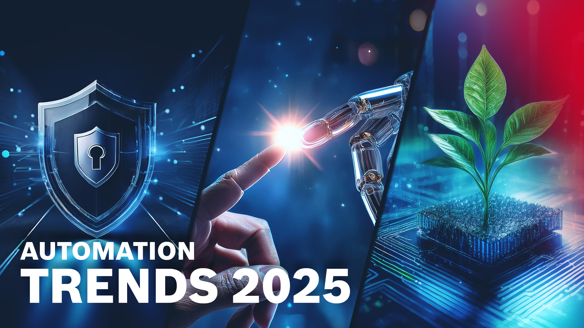
Increased security measures, artificial intelligence and more sustainability. These are the automation trends from Bosch Rexroth’s perspective for the year 2025. (Image source: Bosch Rexroth AG, created with the help of AI)
“Automation remains the key to making the industry future-proof and competitive. It enables efficiency gains, new business models, and added value. We are seeing more and more companies relying on automation platforms with ecosystems, as they offer the greatest possible scope for action. This trend will also continue to increase in 2025,” explains Steffen Winkler, Senior Vice President Sales Business Unit Automation & Electrification Solutions at Bosch Rexroth.
Even greater focus on security with the Cyber Resilience Act
The Cyber Resilience Act (CRA), which came into force at the end of 2024, presents manufacturers and operators of industrial automation systems with new security requirements. The European regulation aims to improve security standards for digital products, thus increasing their resilience to cyber attacks. Products should be securely designed and updatable throughout their entire life cycle.
“IT security is more essential than ever for successful digitization strategies and products. The CRA provides clear requirements – this is an important step toward creating a high level of security across the board and strengthening user confidence in digital solutions. We therefore need to make automation solutions fit for these challenges, as we have already done with our operating system ctrlX OS. It is designed to be secure from the ground up and is therefore ideally prepared for the requirements of the CRA,” says Winkler.
For companies in the automation industry, the CRA means an even more intensive focus on security and product integrity. Adherence to the new directives requires a rethink that starts in product development.
AI is a driver of innovation in automation
Artificial intelligence is set to become even more important in 2025 – including in the automation industry. More and more AI-assisted applications are being integrated into automation systems. AI-assisted apps are already available in the partner network ctrlX World.
Artificial intelligence is increasingly embedded in software. AI-assisted software modules, such as neural networks for image processing solutions, are changing the possibilities for automation. AI also provides new operational insights in practice by analyzing data flows in automation devices. And it changes the way we work, for example, in software development. Tools, such as coding co-pilots, speed up programming and enable code to be written faster.
This enables significant efficiency gains both in the development of automation technologies and in their application.
Sustainability as a strategic goal
Sustainability and energy efficiency will continue to challenge industry and therefore also the automation sector. Industry plays a crucial role in achieving the global climate targets. Sustainable manufacturing requires zero emissions, resource efficiency, and cost-effectiveness.
More and more energy-saving functions are therefore being incorporated into automation components. Tools to simulate energy and performance also make an important contribution to optimizing manufacturing processes. There is further potential in the professional reprocessing of automation components: remanufacturing reduces the carbon footprint of used components by more than 50 percent compared to new products and conserves precious resources.
Open ecosystems for collaborative innovations
“The German automation industry is a global leader. To maintain and expand this leading position, it is essential to strengthen Germany as a business location and to boost the industry’s competitiveness even more,” says Winkler, adding: “Simply being at the technological forefront is not enough to remain successful in global competition in the long term.”
The key lies in open platforms and collaborative ecosystems that create real benefits for users. Such ecosystems combine the strengths of different players and thus enable the development of new, innovative approaches. This creates a culture of collaboration in which partners from different areas work together on solutions that go far beyond the capabilities of individual companies. In addition, open cooperation strengthens users’ trust in digital technologies by providing them with more flexible, interoperable, and future-proof solutions.
Bosch Rexroth constantly drives forward openness and co-creation in the automation world with its operating system ctrlX OS and the automation system ctrlX AUTOMATION.
As one of the world’s leading suppliers of drive and control technologies, Bosch Rexroth ensures efficient, powerful and safe movement in machines and systems of any size. The company bundles global application experience in the market segments of Mobile and Industrial Applications as well as Factory Automation. With its intelligent components, customized system solutions, engineering and services, Bosch Rexroth is creating the necessary environment for fully connected applications. Bosch Rexroth offers its customers hydraulics, electric drive and control technology, gear technology and linear motion and assembly technology, including software and interfaces to the Internet of Things. With locations in over 80 countries, around 33,800 associates generated sales revenue of 7.6 billion euros in 2023.
To learn more, please visit www.boschrexroth.com
CMA/Flodyne/Hydradyne is an authorized Bosch Rexroth distributor in Illinois, Wisconsin, Iowa and Northern Indiana.
In addition to distribution, we design and fabricate complete engineered systems, including hydraulic power units, electrical control panels, pneumatic panels & aluminum framing. Our advanced components and system solutions are found in a wide variety of industrial applications such as wind energy, solar energy, process control and more.
 It is not a surprise that optimizing yield is one of the most important objectives in a sawmill (or


 Simple block diagram: In this example, the logically linked Virtual Instruments read a value from the control unit.
 Quick access to the desired operating interfaces: The SDK for LabVIEW comes with lots of example projects in which the HMI can be quickly and easily adjusted.