Basic operating principle of an Inductive Proximity Sensor

Guest contributor: Henry Menke, Balluff

Did you ever wonder how an Inductive Proximity Sensor is able to detect the presence of a metallic target?  While the underlying electrical engineering is sophisticated, the basic principle of operation is not too hard to understand.

At the heart of an Inductive Proximity Sensor (“prox” “sensor” or “prox sensor” for short) is an electronic oscillator consisting of an inductive coil made of numerous turns of very fine copper wire, a capacitor for storing electrical charge, and an energy source to provide electrical excitation. The size of the inductive coil and the capacitor are matched to produce a self-sustaining sine wave oscillation at a fixed frequency.  The coil and the capacitor act like two electrical springs with a weight hung between them, constantly pushing electrons back and forth between each other.  Electrical energy is fed into the circuit to initiate and sustain the oscillation.  Without sustaining energy, the oscillation would collapse due to the small power losses from the electrical resistance of the thin copper wire in the coil and other parasitic losses.

 Inductive proximity sensor cutaway with annotation

The oscillation produces an electromagnetic field in front of the sensor, because the coil is located right behind the “face” of the sensor.  The technical name of the sensor face is “active surface”.

When a piece of conductive metal enters the zone defined by the boundaries of the electromagnetic field, some of the energy of oscillation is transferred into the metal of the target. This transferred energy appears as tiny circulating electrical currents called eddy currents.  This is why inductive proxes are sometimes called eddy current sensors.

The flowing eddy currents encounter electrical resistance as they try to circulate. This creates a small amount of power loss in the form of heat (just like a little electric heater). The power loss is not entirely replaced by the sensor’s internal energy source, so the amplitude (the level or intensity) of the sensor’s oscillation decreases.  Eventually, the oscillation diminishes to the point that another internal circuit called a Schmitt Trigger detects that the level has fallen below a pre-determined threshold.  This threshold is the level where the presence of a metal target is definitely confirmed.  Upon detection of the target by the Schmitt Trigger, the sensor’s output is switched on.

The short animation to the right shows the effect of a metal target on the sensor’s oscillating magnetic field.  When you see the cable coming out of the sensor turn red, it means that metal was detected and the sensor has been switched on.  When the target goes away, you can see that the oscillation returns to its maximum level and the sensor’s output is switched back off.

Want to learn more about the basic operating principles of Inductive Proximity Sensors? Here’s a short YouTube video covering the basics:

The Future of Hydraulic Systems – HydraSmart

by Bryan Smith, Hydraulic Sales Manager at CMAFH

Automation technology needs are becoming more sophisticated as the industrial marketplace evolves. Efficiency and cost-effectiveness have never been more interrelated, and OEMs need to offer maximum value to stay competitive. The next tech revolution – Industry 4.0 – is here and as we all navigate these uncharted waters, CMAFH is proactively anticipating the need for advanced systems. Our customers have asked for, and we are designing, hydraulic systems that meet the following criteria:

– reduced dB (sound) levels
– reduced heat loads
– greater electrical efficiency

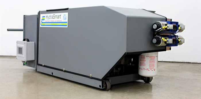
CMAFH designed a hybrid machine packaging hydraulic systems with electrical controls, and we call it HydraSmart. HydraSmart was designed initially to meet the criteria of our Plastics and Machine Tool customers. Working closely with a key customer we created two standard systems that will cover 95% of the industry’s needs.

Hydrasmart is an efficient plug and play HPU that provides variable pressure and flow, easily set by touchscreen. Using the proven technologies of variable speed drives and variable displacement pumps, along with some custom controls, we’ve created a power unit that has a small footprint. In many cases, HydraSmart consumes zero floor space as it is designed to fit within or under many injection molding machines allowing end users to maximize their output per square foot. It will also help your machines to become more energy efficient and much quieter. HydraSmart is typically used with all electric machinery such as injection molding or machine tool/CNC.

World, meet the HydraSmart Power Unit

HYDRAOBLIQUEIMG_7131

HydraSmartIMG_4155

In March of 2015, CMAFH had the opportunity to exhibit at the National Plastics Exhibition in Orlando showing two HydraSmart units as part of a larger display. CMAFH team members Gordon Johnson, Eric Grendahl and I had an exciting week that brought us exposure to thousands of customers. Traffic was steady at the five day event, and visitors were impressed by HydraSmart’s ease of use and small footprint. Pictured below, the ultra-compact HydraSmart unit is designed to reside within the framework of an injection molding machine.

Our efforts and investments in HydraSmart have brought many new and exciting opportunities. As a result, we have moved CMAFH electrical engineer Greg Parkhouse into a new role. Greg is now Special Projects Manager with primary emphasis and focus on the HydraSmart systems. Greg will be working closely with our engineering group, manufacturing group and sales and marketing group as we further develop this product.

If you want to know more about the HydraSmart system, please visit our website. We believe HydraSmart will be an expansive part of our systems business and the future in hydraulic systems.

HydraSmart is typically used with all electric machinery such as injection molding or machine tool/CNC. Learn more about the HydraSmart here or contact us at sales@cmafh.com for more information.

The Future of Cooling Technology in Industrial Enclosures

by Eric Corzine, Product Manager, Climate Control at Rittal

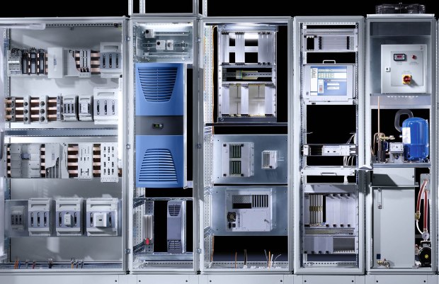
As industrial processes scale, the threats and challenges of cooling the racks of automation equipment increase exponentially. Sophisticated, sensitive electronics and drives are the backbone of many industrial systems. This equipment is often placed inside enclosures to protect it from environmental influences such as temperature, moisture and contaminants like corrosive vapors and dust. If these are not prevented, electronic components will inevitably fail, eventually leading to the shut-down of entire production systems. The failure of a production system can add up to losses for an operation.

What will the future look like?
The single most important environmental factor to manage in industrial enclosures is temperature.  Relative to each individual component, the heat of electronic components has increased significantly in recent years. At the same time, the density inside control cabinets has increased dramatically, resulting in a 50 – 60% increase in heat in the enclosures.

With the advent of microelectronics and new electronic components, the requirements for professional enclosure construction and heat dissipation have evolved dramatically over the last few years. Modern enclosure climate control systems must take these challenges into account, offering the best technical solution while guaranteeing optimum energy efficiency. If heat is not managed properly and the maximum permitted operating temperature is exceeded, the service life of these components is halved and the failure rate is doubled.

Trouble-free operation and functioning of production lines is heavily dependent on how the heat generated by electrical and electronic components is dissipated from the enclosure to the ambient environment. We distinguish three different types methods of heat transfer:

  • Thermal radiation
  • Thermal conduction
  • Convection

In the case of enclosures and electronic housings, we are mainly concerned with thermal conduction and convection. With thermal radiation, heat is passed from one body to another in the form of radiation energy, without a medium material, and plays a minor role here.

Whether we are dealing with heat conduction or convection depends on whether the enclosure is open (air permeable) or closed (air-tight). With an open enclosure, the heat (heat loss) can be dissipated from the enclosure by means of air circulation, i.e. thermal conduction, from inside to outside and is typically in a controlled environment such as data centers. However, if the enclosure has to remain closed due to harsher conditions, the heat can only be dissipated via the enclosure walls, i.e. through convection. Depending on the amount of heat loss of the components, these methods may not sufficiently cool the equipment and a climate control product may be required.

Identifying the proper cooling device depends upon the differences between the ambient temperature (Tu) and the desired enclosure internal temperature (Ti).

An additional factor to consider when choosing a means to cooling is the environment in which the enclosure is installed and the ingress protection (IP) rating required.  Each climate product has corresponding IP ratings:

Other innovative, hybrid cooling technologies have been developed that rely upon two parallel cooling circuits working together depending on the temperature differential. An integral heat pipe dissipates heat from the enclosure when the ambient temperature is below the setpoint, providing passive cooling. Active climatization is achieved when the compressor’s cooling circuit is engaged and provides cooling via speed-controlled components for demand-based cooling. Combining the two circuits reduces temperature hysteresis and provides more precise cooling. Not only is energy consumption far less than with conventional technology, but the improved temperature stability leads to longer service life of both the components within the enclosure and the cooling unit itself.

The reliability of electrical and electronic components in an enclosure can be put at risk not only by excessively high temperatures, but also by excessively low ones. The enclosure interior must be heated, particularly to prevent moisture and protect against frost. It is also necessary to prevent condensation within the enclosure. The latest generation of enclosure heaters has been developed with the help of extensive Computational Fluid Dynamics (CFD) analyses. The positioning of the heater is of fundamental importance for even temperature distribution inside the enclosure. Placement of the heater in the floor area of the enclosure is recommended in order to achieve an optimum distribution of temperature and hence efficiency. Thanks to positive temperature coefficient (PTC) technology, power consumption is reduced at the maximum heater surface temperature. Together with a thermostat, this results in demand-oriented, energy-saving heating.

Smarter, intuitive, and more efficient designs will need to be a staple no matter what setting the enclosure is in.  Designers will need to take careful consideration in the initial planning stages of projects, ensuring that the appropriate cooling technology is incorporated into designs.

ABOUT US

cropped-cmafh-logo-with-tagline-caps.png

CMA/Flodyne/Hydradyne is an authorized  Rittal distributor in Illinois, Wisconsin, Iowa and Northern Indiana.

In addition to distribution, we design and fabricate complete engineered systems, including hydraulic power units, electrical control panels, pneumatic panels & aluminum framing. Our advanced components and system solutions are found in a wide variety of industrial applications such as wind energy, solar energy, process control and more.