Five key technologies shaping warehouse and logistics automation
Reading Time: 5 minutes
In my work at Balluff, I have seen firsthand how intralogistics is evolving through smarter automation. Faster deliveries, real-time tracking, and flexible production are becoming more and more a standard in supply chains. At the same time, companies face labor shortages, skill gaps, and rising demands for efficiency and sustainability.
Automation plays a major role in addressing these challenges, ensuring that operations stay accurate, scalable, and reliable. In a previous post, Automation, Networking and Sensors in Intralogistics, we discussed how industrial networks, sensors, and traceability systems are integrated into everyday warehouse operations.
Let me share some additional thoughts on five key areas of automation technology that continue to shape these processes.
Digitized controls architecture
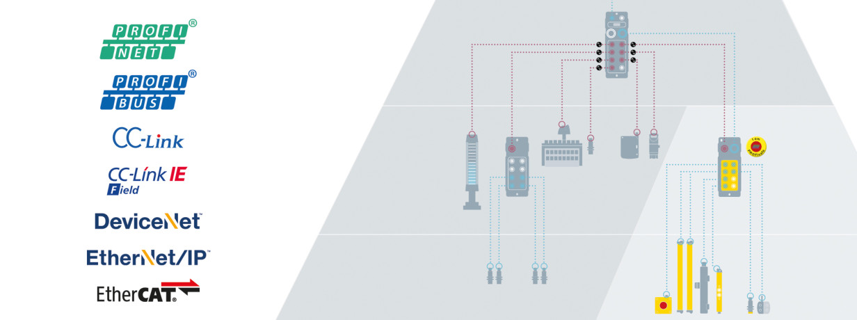
Modern industrial networks make it easier to connect devices to control systems on conveyors, automated storage systems, and robotic platforms. With open standards such as IO-Link, installations become simpler and less expensive because sensor wiring is minimized and diagnostic data is more accessible. Networking also makes system expansion and device replacement faster and simpler; and I have found that this approach not only streamlines installation but also reduces troubleshooting time when issues arise.
Seamless device connectivity through modern networks enhanced by IO-Link masters and hubs reduces complexity, speeds up installation, and simplifies troubleshooting.
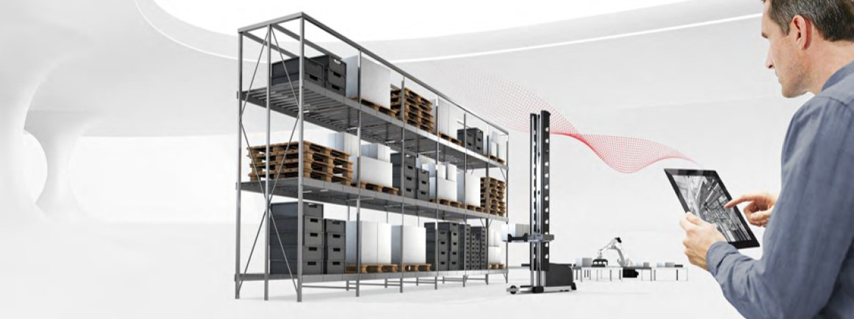
End-to-end traceability
Knowing the location of each package or product at every stage in the facility is key. Whether using RFID or a code reading solution (for example: barcodes, DMC codes, 2D codes), clear identification is important for ensuring the correct handling and movement of goods. In my experience, systems that maintain accurate traceability contribute to improved order accuracy, better transparency and a smoother flow of operations.
Real-time tracking with RFID ensures every package is where it should be, reducing errors and improving process transparency.
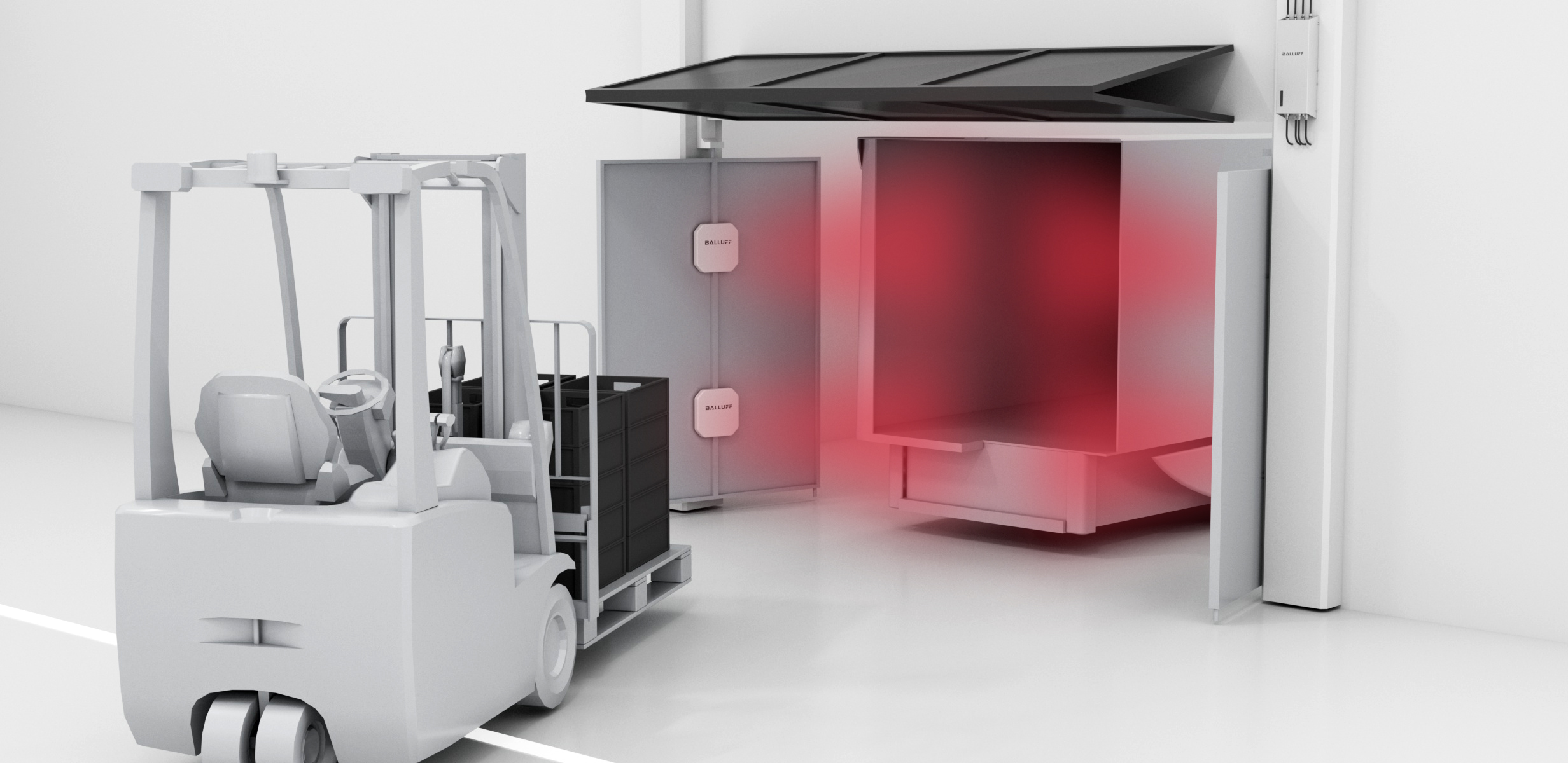
Fast-paced object detection
A range of sensors including photoelectric, inductive, ultrasonic, and capacitive types are used to detect items in real-time. These sensors, integrated with conveyor systems and storage equipment, help monitor the presence, position, and movement of objects. I have observed that accurate object detection leads to more reliable process controls and better overall performance in handling tasks. aben führt.
Photoelectric sensors detect objects, increasing throughput and preventing bottlenecks in high-speed operations.
Condition monitoring of equipment
Preventing unplanned downtime is important in keeping operations running smoothly. By continuously monitoring factors like vibration, temperature, and pressure, condition monitoring systems alert operators to potential issues before they result in a breakdown. This proactive approach can extend equipment life and ensure steady performance across a facility. I’m seeing many companies start with condition monitoring as the first step towards predictive maintenance and improving Overall Equipment Effectiveness.
Continuous monitoring with condition monitoring sensors on conveyor belt motors prevents costly downtime and keeps equipment reliable and productive.
Vision-based systems
Camera systems solve many applications including code reading, quality assurance, palletizing, picking, or placing and sorting. Such systems improve automated handling of a range of products, ensuring accurate identification and placement. For instance, in-line inspection detects damage to goods or packages, minimizing faulty deliveries. In addition, AI-enhanced 3D vision enables collaborative and industrial robots to recognize and pick objects of varying shapes and positions. I see vision technology becoming increasingly important for traceability, object detection, and quality control in intralogistics processes.
AI-powered machine vision enhances automation, making picking, sorting, and quality control more accurate and adaptable.
In summary, each of these technologies plays a key role in future-proofing operations such as conveying and transporting, storage and retrieval, and robotic sorting and picking. In future articles, we’ll take a closer look at these topics and real-world examples.
CMA/Flodyne/Hydradyne is an authorized Balluff distributor in Illinois, Wisconsin, Iowa and Northern Indiana.
In addition to distribution, we design and fabricate complete engineered systems, including hydraulic power units, electrical control panels, pneumatic panels & aluminum framing. Our advanced components and system solutions are found in a wide variety of industrial applications such as wind energy, solar energy, process control and more.