Inductive Proximity Sensor

Where did you find that sensor?

Guest contributor: Shawn Day, Balluff

I recently visited a customer that has a large amount of assembly lines where they have several machine builders manufacturing assembly process lines to their specification. This assembly plant has three different business units and unfortunately, they do not communicate very well with each other. Digging deeper into their error proofing solutions, we found an enormous amount of sensors and cables that could perform the same function, however they mandated different part numbers. This situation was making it very difficult for maintenance employees and machine operators to select the best sensor for the application at hand due to redundancy with their sensor inventory.

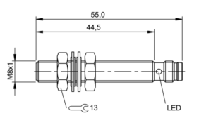
The customer had four different types of M08 Inductive Proximity sensors that all had the same operating specifications with different mechanical specifications. For example, one sensor had a 2mm shorter housing than one of the others in inventory. These 2mm would hardly have an effect when installed into an application 99% of the time. The customer also had other business units using NPN output polarity VS PNP polarity making it even more difficult to select the correct sensor and in some situations adding even more downtime when the employee tried to replace an NPN sensor where a PNP offering was needed. As we all know, the NPN sensor looks identical to the PNP offering just by looking at it. One would have to really understand the part number breakdown when selecting the sensor, and when a machine is down this sometimes can be overlooked. This is why it is so important to standardize on sensor selection when possible. This will result in more organized inventory by reducing part numbers, reducing efforts from purchasing and more importantly offering less confusion for the maintenance personel that keep production running.

Below are five examples of M08 Inductive sensors that all have the same operating specifications. You will notice the difference in housing lengths and connection types. You can see that there can be some confusion when selecting the best one for a broad range of application areas. For example, the housing lengths are just a few millimeters different. You can clearly see that one or two of these offerings could be installed into 99% of the application areas where M08 sensors are needed for machine or part position or simply error proofing a process.

Shawn1Shawn2.pngShawn3Shawn4                                                             Shawn5

For more information on standardizing your sensor selection visit www.balluff.com

cropped-cmafh-logo-with-tagline-caps.pngCMA/Flodyne/Hydradyne is an authorized  Balluff distributor in Illinois, Wisconsin, Iowa and Northern Indiana.

In addition to distribution, we design and fabricate complete engineered systems, including hydraulic power units, electrical control panels, pneumatic panels & aluminum framing. Our advanced components and system solutions are found in a wide variety of industrial applications such as wind energy, solar energy, process control and more.

Reliable Part Exit/Part-Out Detection

Guest contributor: Dave Bird, Balluff

Walk into any die shop in the US and nine out of ten times, we discover diffuse reflective sensors being used to detect a large part or a small part exiting a die. Many people have success using this methodology, but lubrication-covered tumbling parts can create challenges for diffuse-reflective photoelectric sensing devices for many reasons:

  1. Tumbling parts with many “openings” on the part itself can cause a miss-detected component.
  2. Overly-reflective parts can false triggering of the output.
  3. Dark segments of the exiting part can cause light absorption. Remember, a diffuse sensors sensing distance is based on reflectivity. Black or dark targets tend to absorb light and not reflect light back to the receiver.
  4. Die lube/misting can often fog over a photoelectric lens requiring maintenance or machine down time.

The solution: Super Long Range Inductive Sensors placed under chutes

Most metal forming personnel are very familiar with smaller versions of inductive proximity sensors in tubular sizes ranging from 3mm through 30mm in diameter and with square or “block style” inductive types (flat packs, “pancake types”, etc.) but it is surprising how many people are just now discovering “Super Long Range Inductive Proximity” types. Super Long Range Inductive Proximity Sensors have been used in metal detection applications for many years including Body-In-White Automotive applications, various segments of steel processing and manufacturing, the canning industry, and conveyance.

Benefits of Using A UHMW Chute + Super Long Range Inductive Proximity Sensor in Part Exit/Part-Out Applications:

  1. It is stronger and quieter than parts flowing over a metal chute, readily available in standard and custom widths, lengths and thicknesses to fit the needs of large and small part stampers everywhere.
  2. UHMW is reported to be 3X stronger than carbon steel.
  3. UHMW is resistant to die lubes.
  4. UHMW allows Super Long Range Inductive Proximity Sensors to be placed underneath and to be “tuned” to fit the exact zone dimension required to detect any part exiting the die (fixed ranges and tunable with a potentiometer). The sensing device is also always out of harm’s way.
  5. Provides an option for part detection in exiting applications that eliminates potential problems experienced in certain metal forming applications where photoelectric sensing solutions aren’t performing optimally.

A Two-Out Die with Metallic Chute

Not every Part Exit/Part-Out application is the same and not every die, stamping application, vintage of equipment, budget for sensing programs are the same. Butit’s important to remember in the world of stamping, to try as consistently as possible to think application specificity when using sensors.  That is, putting the right sensing system in the right place to get the job done and to have as many technical options available as possible to solve application needs in your own “real world” metal forming operation.  We believe the UHMW + Super Long Range Inductive System is such an option.

You can learn more in the video below or by visiting www.balluff.us.


cropped-cmafh-logo-with-tagline-caps.pngCMA/Flodyne/Hydradyne is an authorized  Balluff distributor in Illinois, Wisconsin, Iowa and Northern Indiana.

In addition to distribution, we design and fabricate complete engineered systems, including hydraulic power units, electrical control panels, pneumatic panels & aluminum framing. Our advanced components and system solutions are found in a wide variety of industrial applications such as wind energy, solar energy, process control and more.

Basic operating principle of an Inductive Proximity Sensor

Guest contributor: Henry Menke, Balluff

Did you ever wonder how an Inductive Proximity Sensor is able to detect the presence of a metallic target?  While the underlying electrical engineering is sophisticated, the basic principle of operation is not too hard to understand.

At the heart of an Inductive Proximity Sensor (“prox” “sensor” or “prox sensor” for short) is an electronic oscillator consisting of an inductive coil made of numerous turns of very fine copper wire, a capacitor for storing electrical charge, and an energy source to provide electrical excitation. The size of the inductive coil and the capacitor are matched to produce a self-sustaining sine wave oscillation at a fixed frequency.  The coil and the capacitor act like two electrical springs with a weight hung between them, constantly pushing electrons back and forth between each other.  Electrical energy is fed into the circuit to initiate and sustain the oscillation.  Without sustaining energy, the oscillation would collapse due to the small power losses from the electrical resistance of the thin copper wire in the coil and other parasitic losses.

 Inductive proximity sensor cutaway with annotation

The oscillation produces an electromagnetic field in front of the sensor, because the coil is located right behind the “face” of the sensor.  The technical name of the sensor face is “active surface”.

When a piece of conductive metal enters the zone defined by the boundaries of the electromagnetic field, some of the energy of oscillation is transferred into the metal of the target. This transferred energy appears as tiny circulating electrical currents called eddy currents.  This is why inductive proxes are sometimes called eddy current sensors.

The flowing eddy currents encounter electrical resistance as they try to circulate. This creates a small amount of power loss in the form of heat (just like a little electric heater). The power loss is not entirely replaced by the sensor’s internal energy source, so the amplitude (the level or intensity) of the sensor’s oscillation decreases.  Eventually, the oscillation diminishes to the point that another internal circuit called a Schmitt Trigger detects that the level has fallen below a pre-determined threshold.  This threshold is the level where the presence of a metal target is definitely confirmed.  Upon detection of the target by the Schmitt Trigger, the sensor’s output is switched on.

The short animation to the right shows the effect of a metal target on the sensor’s oscillating magnetic field.  When you see the cable coming out of the sensor turn red, it means that metal was detected and the sensor has been switched on.  When the target goes away, you can see that the oscillation returns to its maximum level and the sensor’s output is switched back off.

Want to learn more about the basic operating principles of Inductive Proximity Sensors? Here’s a short YouTube video covering the basics: