Sensors

Hydraulic Valves Will Benefit From Connectivity

Guest contributor, Jeroen Brands, Bosch Rexroth

Hydraulic valves: Directional valve with integrated digital axis controller

Hydraulic valves: Directional valve with integrated digital axis controller

What are the current market requirements for hydraulic valves?

We are currently experiencing a transition from classic, analogous hydraulics to connectable digital fluid technology. European machine manufacturers in particular are increasingly digitizing their machine designs and expect that hydraulics can be seamlessly embedded into these connected environments. This means that regarding the level of automation, hydraulics are on a par with electromechanical drives. One of the decisive features in this respect is the seamless integration of intelligent hydraulic valves into different automation topologies via open standards such as multiple Ethernet interfaces.

Which new technical possibilities are available to meet these requirements?

Smart single-axis controllers are already remotely regulating hydraulic motions in a closed control loop. In addition, a powerful motion control is integrated into the on-board electronics of the valve. It performs the target-actual comparison on site and regulates accurately to a few micrometers. The control quality of the system is exclusively determined by the resolution of the measurement systems. These motion controls without control cabinet are increasingly used in saw lines, paper mills and machine tools. In addition, there are smart variable speed pump drives and smart pump controls. They provide completely new possibilities of replacing the throttle controls, which were predominantly used up to now, by more energy-efficient displacement controls. In this way, functions which were previously executed by valves are relocated to the software.

What about the integration of sensor technology into hydraulic valves?

The mass production of sensors for the automotive or the consumer products industry has significantly reduced the costs. Now, sensors are increasingly used in hydraulics. In our opinion, the integration of sensor technology of this kind into existing valve housings is the next step. Regarding condition monitoring, sensors could collect information on fluid quality, temperature, vibrations and performed switching cycles. Via deep learning algorithms, users can then detect wear before it causes malfunction.

Which other possibilities of mechanization does a valve provide?

The degree of freedom regarding connection geometries is already limited by standard requirements. The hydraulics industry discussed the topic of digital hydraulics in great depth some time ago. The idea was and is to control flows in a “stepped” or “clocked” way using single- or multi-bit strategies. In certain applications, this can constitute an advantage compared to continuously variable technology.

Which other innovations in hydraulic valves are relevant in your company?

It is no longer a question whether hydraulic valve technology will benefit from connectivity or not. The only question is when. The current discussions around Industry 4.0 clearly show how important it is to define all required functions and functionalities. Only if mechanisms and sensor technology are standardized across different manufacturers will active connectivity and communication be possible. Even in the future, not every hydraulic-mechanical pressure valve will have digital electronics on board or be connected to a control system or other valves. An imprinted QR code with information on the manufacturer’s settings, functional descriptions or information on replacement seals are a first step towards connectivity. In the area of new materials and production technologies, Rexroth has many innovations in the pipeline. 3D printing of cores for cast housings or direct printing considerably lowers energy consumption during the operation of valves. While the divisibility of the core mold had to be taken into account in the design of the core, this is no longer necessary today thanks to core printing. This means that we can use other channel designs which allow for lower pressure losses and improve energy consumption. For a valve with a flow of 10,000 l/min, the reduction of flow resistance by 10 to 20 percent significantly reduces the operating expenses.

Pressure transducer for hydraulic applications

How do these trends affect your products?

With the IAC (integrated axis controller) valves, Bosch Rexroth offers motion control without control cabinet which is completely integrated into valve electronics. It can be fully connected via open interfaces. The same applies to servo-hydraulic axes with their own fluid circuit. In these ready-to-mount axes, pump, valves and cylinders form an assembly to which the machine manufacturer only has to connect power supply and control communication. They use the same commissioning tools and user interfaces which means that all drive technologies provide the same look and feel. Classic servo valves, however, can also be improved further. New plug-in amplifiers with pulse width modulation for on/off valves by Rexroth reduce the surface temperature of the connectors by more than 80 degrees to only 50 degrees. This is particularly interesting for saw lines where easily inflammable sawdust constitutes an explosion hazard.

Outlook: How will valve technology change in the next 10 years?

In 10 years, valves will allow for easier project planning, more comfortable commissioning and more efficient operation and will provide more information before a service case. If service is required, the valve may already have ordered its spare parts.


cropped-cmafh-logo-with-tagline-caps.pngCMA/Flodyne/Hydradyne is an authorized Bosch Rexroth distributor in Illinois, Wisconsin, Iowa and Northern Indiana.

In addition to distribution, we design and fabricate complete engineered systems, including hydraulic power units, electrical control panels, pneumatic panels & aluminum framing. Our advanced components and system solutions are found in a wide variety of industrial applications such as wind energy, solar energy, process control and more.

Improve Your Feeder Bowl System (and Other Standard Equipment) with IO-Link

Guest contributor: Tom Rosenberg, Balluff

One of the most common devices used in manufacturing is the tried and true feeder bowl system. Used for decades, feeder bowls take bulk parts, orient them correctly and then feed them to the next operation, usually a pick-and-place robot. It can be an effective device, but far too often, the feeder bowl can be a source of cycle-time slowdowns. Alerts are commonly used to signal when a feed problem is occurring but lack the exact cause of the slow down.

feeder bowl

A feed system’s feed rate can be reduced my many factors. Some of these include:

  • Operators slow to add parts to the bowl or hopper
  • Hopper slow to feed the bowl
  • Speeds set incorrectly on hopper, bowl or feed track
  • Part tolerance drift or feeder tooling out of adjustment

With today’s Smart IO-Link sensors incorporating counting and timing functions, most of the slow-down factors can be easily seen through an IIoT connection. Sensors can now time how long critical functions take. As the times drift from ideal, this information can be collected and communicated upstream.

A common example of a feed system slow-down is a slow hopper feed to the bowl. When using Smart IO-Link sensors, operators can see specifically that the hopper feed time is too long. The sensor indicates a problem with the hopper but not the bowl or feed tracks. Without IO-Link, operators would simply be told the overall feed system is slow and not see the real problem. This example is also true for the hopper in-feed (potential operator problem), feed track speed and overall performance. All critical operations are now visible and known to all.

For examples of Balluff’s smart IO-Link sensors, check out our ADCAP sensor.


cropped-cmafh-logo-with-tagline-caps.pngCMA/Flodyne/Hydradyne is an authorized  Balluff distributor in Illinois, Wisconsin, Iowa and Northern Indiana.

In addition to distribution, we design and fabricate complete engineered systems, including hydraulic power units, electrical control panels, pneumatic panels & aluminum framing. Our advanced components and system solutions are found in a wide variety of industrial applications such as wind energy, solar energy, process control and more.

Where did you find that sensor?

Guest contributor: Shawn Day, Balluff

I recently visited a customer that has a large amount of assembly lines where they have several machine builders manufacturing assembly process lines to their specification. This assembly plant has three different business units and unfortunately, they do not communicate very well with each other. Digging deeper into their error proofing solutions, we found an enormous amount of sensors and cables that could perform the same function, however they mandated different part numbers. This situation was making it very difficult for maintenance employees and machine operators to select the best sensor for the application at hand due to redundancy with their sensor inventory.

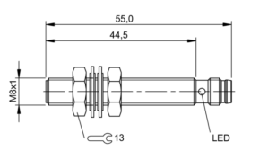
The customer had four different types of M08 Inductive Proximity sensors that all had the same operating specifications with different mechanical specifications. For example, one sensor had a 2mm shorter housing than one of the others in inventory. These 2mm would hardly have an effect when installed into an application 99% of the time. The customer also had other business units using NPN output polarity VS PNP polarity making it even more difficult to select the correct sensor and in some situations adding even more downtime when the employee tried to replace an NPN sensor where a PNP offering was needed. As we all know, the NPN sensor looks identical to the PNP offering just by looking at it. One would have to really understand the part number breakdown when selecting the sensor, and when a machine is down this sometimes can be overlooked. This is why it is so important to standardize on sensor selection when possible. This will result in more organized inventory by reducing part numbers, reducing efforts from purchasing and more importantly offering less confusion for the maintenance personel that keep production running.

Below are five examples of M08 Inductive sensors that all have the same operating specifications. You will notice the difference in housing lengths and connection types. You can see that there can be some confusion when selecting the best one for a broad range of application areas. For example, the housing lengths are just a few millimeters different. You can clearly see that one or two of these offerings could be installed into 99% of the application areas where M08 sensors are needed for machine or part position or simply error proofing a process.

Shawn1Shawn2.pngShawn3Shawn4                                                             Shawn5

For more information on standardizing your sensor selection visit www.balluff.com

cropped-cmafh-logo-with-tagline-caps.pngCMA/Flodyne/Hydradyne is an authorized  Balluff distributor in Illinois, Wisconsin, Iowa and Northern Indiana.

In addition to distribution, we design and fabricate complete engineered systems, including hydraulic power units, electrical control panels, pneumatic panels & aluminum framing. Our advanced components and system solutions are found in a wide variety of industrial applications such as wind energy, solar energy, process control and more.

Imagine the Perfect Photoelectric Sensor

Guest contributor: Jack Moermond, Balluff

Photoelectric sensors have been around for a long time and have made huge advancements in technology since the 1970’s.  We have gone from incandescent bulbs to modulated LED’s in red light, infrared and laser outputs.  Today we have multiple sensing modes like through-beam, diffuse, background suppression, retroreflective, luminescence, distance measuring and the list goes on and on.  The outputs of the sensors have made leaps from relays to PNP, NPN, PNP/NPN, analog, push/pull, triac, to having timers and counters and now they can communicate on networks.

The ability of the sensor to communicate on a network such as IO-Link is now enabling sensors to be smarter and provide more and more information.  The information provided can tell us the health of the sensor, for example, whether it needs re-alignment to provide us better diagnostics information to make troubleshooting faster thus reducing downtimes.  In addition, we can now distribute I/O over longer distances and configure just the right amount of IO in the required space on the machine reducing installation time.

IO-Link networks enable quick error free replacement of sensors that have failed or have been damaged.  If a sensor fails, the network has the ability to download the operating parameters to the sensor without the need of a programming device.

With all of these advancements in sensor technology why do we still have different sensors for each sensing mode?  Why can’t we have one sensor with one part number that would be completely configurable?

BOS21M_Infographic_112917

Just think of the possibilities of a single part number that could be configured for any of the basic sensing modes of through-beam, retroreflective, background suppression and diffuse. To be able to go from 30 or more part numbers to one part would save OEM’s end users a tremendous amount of money in spares. To be able to change the sensing mode on the fly and download the required parameters for a changing process or format change.  Even the ability to teach the sensing switch points on the fly, change the hysteresis, have variable counter and time delays.  Just imagine the ability to get more advanced diagnostics like stress level (I would like that myself), lifetime, operating hours, LED power and so much more.

Obviously we could not have one sensor part number with all of the different light sources but to have a sensor with a light source that could be completely configurable would be phenomenal.  Just think of the applications.  Just think outside the box.  Just imagine the possibilities.  Let us know what your thoughts are.

To learn more about photoelectric sensors, visit www.balluff.com.

cropped-cmafh-logo-with-tagline-caps.pngCMA/Flodyne/Hydradyne is an authorized  Balluff distributor in Illinois, Wisconsin, Iowa and Northern Indiana.

In addition to distribution, we design and fabricate complete engineered systems, including hydraulic power units, electrical control panels, pneumatic panels & aluminum framing. Our advanced components and system solutions are found in a wide variety of industrial applications such as wind energy, solar energy, process control and more.

5 Ways Flexible Manufacturing has Never Been Easier

Guest Contributor: Tom Rosenberg, Balluff

Flexible manufacturing has never been easier or more cost effective to implement, even down to lot-size-one, now that IO-Link has become an accepted standard. Fixed control and buried information is no longer acceptable. Driven by the needs of IIoT and Industry 4.0, IO-Link provides the additional data that unlocks the flexibility in modern automation equipment, and it’s here now!  As evidence, here are the top five examples of IO-Link enabled flexibility:

#5. Quick Change Tooling: The technology of inductive coupling connects standard IO-Link devices through an airgap. Change parts and End of Arm (EOA) tooling can quickly and reliably be changed and verified while maintaining connection with sensors and pneumatic valves. This is really cool technology…power through the air!

Image1


#4. On-the-fly Sensors Programming: Many sensor applications require new settings when the target changes, and the targets seem to always change. IO-Link enables this at minimal cost and very little time investment. It’s just built in.

Image 2


#3. Flexible Indicator Lights: Detailed communication with the operators no long requires a traditional HMI. In our flexible world, information such as variable process data, timing indication, machine status, run states and change over verification can be displayed at the point of use. This represents endless creativity possibilities.

Powertrain visualisieren


#2. Low cost RFID: Radio Frequency Identification (RFID) has been around for a while. But with the cost point of IO-Link, the applications have been rapidly climbing. From traditional manufacturing pallets to change-part tracking, the ease and cost effectiveness of RFID is at a record level. If you have ever thought about RFID, now is the time.

7_1_Produktionsdaten_Dokumentieren


#1. Move Away from Discrete to Continuously Variable Sensors: Moving from discrete, on-off sensors to continuously variable sensors (like analog but better) opens up tremendous flexibility. This eliminates multiple discrete sensors or re-positioning of sensors. One sensor can handle multiple types and sizes of products with no cost penalty. IO-Link makes this more economical than traditional analog with much more information available. This could be the best technology shift since the move to Ethernet based I/O networks.

8_1_induktiver_Abstand

So #1 was the move to Continuously Variable sensors using IO-Link. But the term, “Continuously Variable” doesn’t just roll off the tongue. We have discrete and analog sensors, but what should we call these sensors? Let me know your thoughts!

To learn more about RFID and IO-Link technology, visit www.balluff.com.

cropped-cmafh-logo-with-tagline-caps.pngCMA/Flodyne/Hydradyne is an authorized  Balluff distributor in Illinois, Wisconsin, Iowa and Northern Indiana.

In addition to distribution, we design and fabricate complete engineered systems, including hydraulic power units, electrical control panels, pneumatic panels & aluminum framing. Our advanced components and system solutions are found in a wide variety of industrial applications such as wind energy, solar energy, process control and more.

Reliable Part Exit/Part-Out Detection

Guest contributor: Dave Bird, Balluff

Walk into any die shop in the US and nine out of ten times, we discover diffuse reflective sensors being used to detect a large part or a small part exiting a die. Many people have success using this methodology, but lubrication-covered tumbling parts can create challenges for diffuse-reflective photoelectric sensing devices for many reasons:

  1. Tumbling parts with many “openings” on the part itself can cause a miss-detected component.
  2. Overly-reflective parts can false triggering of the output.
  3. Dark segments of the exiting part can cause light absorption. Remember, a diffuse sensors sensing distance is based on reflectivity. Black or dark targets tend to absorb light and not reflect light back to the receiver.
  4. Die lube/misting can often fog over a photoelectric lens requiring maintenance or machine down time.

The solution: Super Long Range Inductive Sensors placed under chutes

Most metal forming personnel are very familiar with smaller versions of inductive proximity sensors in tubular sizes ranging from 3mm through 30mm in diameter and with square or “block style” inductive types (flat packs, “pancake types”, etc.) but it is surprising how many people are just now discovering “Super Long Range Inductive Proximity” types. Super Long Range Inductive Proximity Sensors have been used in metal detection applications for many years including Body-In-White Automotive applications, various segments of steel processing and manufacturing, the canning industry, and conveyance.

Benefits of Using A UHMW Chute + Super Long Range Inductive Proximity Sensor in Part Exit/Part-Out Applications:

  1. It is stronger and quieter than parts flowing over a metal chute, readily available in standard and custom widths, lengths and thicknesses to fit the needs of large and small part stampers everywhere.
  2. UHMW is reported to be 3X stronger than carbon steel.
  3. UHMW is resistant to die lubes.
  4. UHMW allows Super Long Range Inductive Proximity Sensors to be placed underneath and to be “tuned” to fit the exact zone dimension required to detect any part exiting the die (fixed ranges and tunable with a potentiometer). The sensing device is also always out of harm’s way.
  5. Provides an option for part detection in exiting applications that eliminates potential problems experienced in certain metal forming applications where photoelectric sensing solutions aren’t performing optimally.

A Two-Out Die with Metallic Chute

Not every Part Exit/Part-Out application is the same and not every die, stamping application, vintage of equipment, budget for sensing programs are the same. Butit’s important to remember in the world of stamping, to try as consistently as possible to think application specificity when using sensors.  That is, putting the right sensing system in the right place to get the job done and to have as many technical options available as possible to solve application needs in your own “real world” metal forming operation.  We believe the UHMW + Super Long Range Inductive System is such an option.

You can learn more in the video below or by visiting www.balluff.us.


cropped-cmafh-logo-with-tagline-caps.pngCMA/Flodyne/Hydradyne is an authorized  Balluff distributor in Illinois, Wisconsin, Iowa and Northern Indiana.

In addition to distribution, we design and fabricate complete engineered systems, including hydraulic power units, electrical control panels, pneumatic panels & aluminum framing. Our advanced components and system solutions are found in a wide variety of industrial applications such as wind energy, solar energy, process control and more.
3 Tips for Reducing Downtime

Guest contributor:  Janet Czubek, Balluff

Whether it’s through preventative maintenance or during planned machine downtime, reducing downtime is a common goal for manufacturers. Difficult environments create challenges for not just machines, but also the components like sensors or cables. Below are three tips to help protect these components and reduce your downtime.

sacraficialcableCables don’t last forever. However, they are important for operations and keeping them functional is vital. An easy way to help reduce downtime and save money is by implementing a “sacrificial cable” in unforgiving environments. A sacrificial cable is any cable less than two meters in length and placed in situations where there is high turnover of cables.  This sacrificial cable does not have to be a specialty cable with a custom jacket. It can be a simple 1 meter PVC cable that will get changed out often. The idea is to place a sacrificial cable in a problematic area and connect it to a longer length cable, or a home-run cable. The benefits of this method include: less downtime for maintenance when changing out failures, reduced expenses since shorter cables are less expensive, and there is less travel for the cable around a cell.

hdc_cablesA second way to help reduce downtime is consider your application conditions up front. We discussed some of the application conditions to consider in a previous blog post, but how can we address these challenges? Not only is it important to choose the correct sensor for the environment, but remember, cables don’t last forever. Choosing the appropriate cable is also key to reducing downtime. Welding environments demand a cable that weld beads will not stick to and fuse the cable to the sensor. There are a variety of jacket types like silicone, silicone tube, or PTFE that prevent weld debris from accumulating on the cable. I’ve also seen applications where there is a lot of debris cutting through cables. In this case, a stainless steel braid cable would be a better solution than a traditional cable. Fitting the right protection to the right application is crucial..

gizmo4A third tip to help reduce your machine downtime is to simply add protection to your existing components. Adding protection, whether it is a protective bracket or a silicone product, will help keep components running longer. This type of protection can be added before or after the cell is operational.   One example of sensor protection is adding a ceramic cap to protect the face of a sensor. You can also protect the connection by adding tubing to the cable out version of the sensor to shield it from debris. Mounting sensors in a robust bracket helps protect the sensor from being hit, or having debris cover the sensor.  There are different degrees of changes that help prolong operations.

Metalforming expert, Dave Bird, explains some of these solutions in the video below. To learn more you can also visit our website at www.balluff.us.

About Us

cropped-cmafh-logo-with-tagline-caps.png


CMA/Flodyne/Hydradyne is an authorized  Balluff distributor in Illinois, Wisconsin, Iowa and Northern Indiana.

In addition to distribution, we design and fabricate complete engineered systems, including hydraulic power units, electrical control panels, pneumatic panels & aluminum framing. Our advanced components and system solutions are found in a wide variety of industrial applications such as wind energy, solar energy, process control and more.

A Simple Out Feed Solution for Progressive Stamping

Guest contributor: Dave Bird, Balluff

Applications where sensor contact is unavoidable are some of the most challenging to solve. Metal forming processes involving over travel can also damage or even destroy a sensor causing failure and expensive unplanned downtime. Manufacturers often try to remedy this with in-house manufactured spring loaded out-feed mechanisms but those are expensive to make by experienced tool and die personnel who have more important things to do . Over the years, I’ve seen this as a pervasive problem in the stamping industry. Many of these issues can be solved with the use of a simple yet effective  sensor actuator system known as a Balluff PlungerProx.

PlungerProx solves a few key issues in Progressive stamping:

  • The flexible trigger/actuation point is fully adjustable to meet sensitive or less sensitive activation points, not possible with “fixed” systems with substantial “over travel” built into the design.
  • It is fully self-contained (minimizing any risk of sensor damage and resulting unplanned machine down time).
  • The device can be disassembled and rapidly cleaned, reassembled, and placed back in service in the event that die lube or other industrial fluids enter the M18 body that can potentially congeal during shut down periods.

See me demo this product in the following video:

About Us

cropped-cmafh-logo-with-tagline-caps.png

CMA/Flodyne/Hydradyne is an authorized  Balluff distributor in Illinois, Wisconsin, Iowa and Northern Indiana.

In addition to distribution, we design and fabricate complete engineered systems, including hydraulic power units, electrical control panels, pneumatic panels & aluminum framing. Our advanced components and system solutions are found in a wide variety of industrial applications such as wind energy, solar energy, process control and more.

To avoid trouble later, consider your application conditions upfront

Guest contributor: Henry Menke, Balluff

Hardly a day passes by where we are not contacted by a desperate end-user or equipment manufacturer seeking assistance with a situation of sensors failing at an unacceptably high rate.  Once we get down to the root cause of the failures, in almost every case it’s a situation where the specific sensors are being applied in a manner which all but guarantees premature failure.

Not all sensors are created equal.  Some are intentionally designed for light-duty applications where the emphasis is more on economical cost rather than the ability to survive in rough service conditions.  Other sensors are specifically designed to meet particular challenges of the application environment and as a result may carry a higher initial price.

Some things to think about when choosing a sensor for a new application:

  • What kind of environmental conditions will the sensor be exposed to?  For example:
    • Very low or very high temperatures
    • Constant exposure to or immersion in liquid water
    • Continuous vibration
    • Extreme shock
    • Disruptive electrical noise (hand-held radios, welding fields, etc.)
    • Chemical contamination
    • Physical abuse or impact
    • Abrasion
    • High pressure wash down procedures
    • Exposure to outdoor conditions of UV sunlight, rain, ice, temperature swings, and condensing humidity
  • Is it possible to relocate the sensor to move it away from the difficult condition?
  • Is the sensor technology the best choice given the kind of application environment that it must operate in?
  • Is there a way to protect the sensor from exposure to the worst of the damaging effects?

When you reach for a catalog or jump on the internet to look for a sensor, it’s a good practice to just stop a moment first and make a list of the environmental challenges that the sensor could face.  Then you will be prepared to make an appropriate selection that best meets your expected application conditions.

About Us

cropped-cmafh-logo-with-tagline-caps.png

CMA/Flodyne/Hydradyne is an authorized  Balluff distributor in Illinois, Wisconsin, Iowa and Northern Indiana.

In addition to distribution, we design and fabricate complete engineered systems, including hydraulic power units, electrical control panels, pneumatic panels & aluminum framing. Our advanced components and system solutions are found in a wide variety of industrial applications such as wind energy, solar energy, process control and more.

Acids Can Put Your Sensors in a Pickle

Guest contributor,  Henry Menke, Balluff

In many types of metals production, pickling is a process that is essential to removing impurities and contaminants from the surface of the material prior to further processing, such as the application of anti-corrosion coatings.

In steel production, two common pickling solutions or pickle liquors are hydrochloric acid (HCl) and sulfuric acid (H2SO4). Both of these acids are very effective at removing rust and iron oxide scale from the steel prior to additional processing, for example galvanizing or rolling. The choice of acid depends on the processing temperature, the type of steel being processed, and environmental containment and recovery considerations. Hydrochloric acid creates corrosive fumes when heated, so it typically must be used at lower temperatures where processing times are longer. It is also more expensive to recover when spent. Sulfuric acid can be used at higher temperatures for faster processing, but it can attack the base metal more aggressively and create embrittlement due to hydrogen diffusion into the metal.

Acids can be just as tough on all of the equipment involved in the pickling lines, including sensors. When selecting sensors for use in areas involving liquid acid solutions and gaseous fumes and vapors, care must be given to the types of acids involved and to the materials used in the construction of the sensor, particularly the materials that may be in direct contact with the media.

PressureSensor

A pressure sensor specifically designed for use with acidic media, at temperatures up to 125 degrees C.

A manufacturer of silicon steel was having issues with frequent failure of mechanical pressure sensors on the pickling line, due to the effects of severe corrosion from hydrochloric acid at 25% concentration. After determination of the root cause of these failures and evaluation of alternatives, the maintenance team selected an electronic pressure sensor with a process connection custom-made from PVDF (polyvinylidene fluoride), a VitonTM O-ring, and a ceramic (rather than standard stainless steel) pressure diaphragm. This changeover eliminated the corroded mechanical pressure sensors as an ongoing maintenance problem, increasing equipment availability and freeing up maintenance personnel to address other issues on the line.