Balluff

Safely Switch Off Cylinders While Transmitting Field Data

Guest contributor: Matthias Wolfer, Balluff


Is it possible to safely switch off cylinders while simultaneously transmitting field data and set up the system in accordance with standards? Yes!

In order to rule out a safety-critical fault between adjacent printed circuit board tracks/contact points (short circuit) according to DIN EN ISO 13849, clearance and creepage distances must be considered. One way to eliminate faults is to provide galvanic isolation by not interconnecting safety-relevant circuits/segments. This means  charge carriers from one segment cannot switch over to the other, and the separation makes it possible to connect the safety world with automation — with IO-Link. Safely switching off actuators and simultaneously collecting sensor signals reliably via IO-Link is possible with just one module. To further benefit from IO-Link and ensure safety at the same time, Balluff’s I/O module is galvanically isolated with a sensor and an actuator segment. The two circuits of the segments are not interconnected, and the actuator segment can be safely switched off without affecting the sensors. Important sensor data can still be monitoring and communicated.

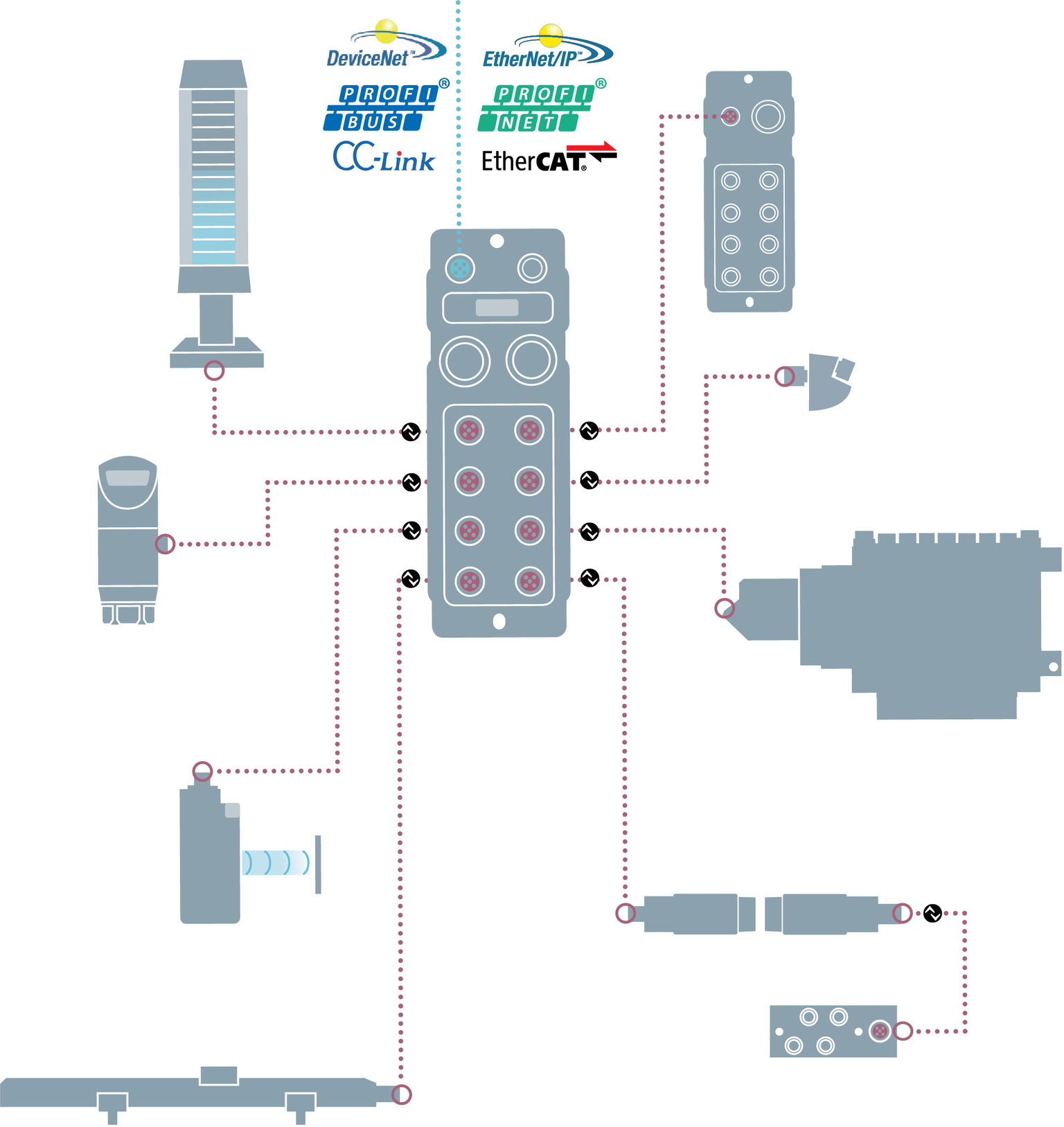
The topological structure and the application of this safety function is shown in this figure as an example:

2D-SAGT-Betriebsanleitung_v2

  1. A PLC is connected to an IO-Link master module via a fieldbus system.
  2. The IO-Link master is the interface to all I/O modules (IO-Link sensor/actuator hubs) or other devices, such as IO-Link sensors. The IO-Link communication takes place via a standardized M12 connector.|
  3. Binary switching elements can be connected to the galvanically isolated sensor/actuator hub (BNI IOL-355). The four connection ports on the left correspond to the sensor segment and the four ports on the right correspond to the actuator segment. Communication of the states is done via IO-Link.
  4. The power supply for both segments takes place via a 7/8″ connection, whereby attention must be paid to potential separated routing of the sensor and actuator circuits. Both the power supply unit itself and the wiring to the IO-Link device with the two segments must also ensure external galvanic isolation. This is made possible by separating the lines with a splitter.
  5. An external safety device is required to safely interrupt the supply voltage of the actuator segment (four ports simultaneously). Thus, the module can implement safety functions up to SIL2 according to EN62061/PLd and ISO 13849.

For example, this can happen through the use of a safety relay, whereby the power supply is safely disconnected after actuation of peripheral safety devices (such as emergency stops and door switches). At the same time, the sensor segment remains active and can provide important information from the field devices.

The module can handle up to eight digital inputs and outputs. If the IO-Link connection is interrupted, the outputs assume predefined states that are retained until the IO-Link connection is restored. Once the connection is restored, this unique state of the machine can be used to continue production directly without a reference run.

An application example for the interaction of sensors and actuators in a safety environment is the pneumatic clamping device of a workpiece holder. The position feedback of the cylinders is collected by the sensor segment, while at the same time the actuator segment can be switched off safely via its separately switchable safety circuit. If the sensor side is not required for application-related reasons, galvanically isolated IO-Link modules are also available with only actuator segments (BNI IOL 252/256). An isolated shutdown can protect up to two safety areas separately.

cropped-cmafh-logo-with-tagline-caps.pngCMA/Flodyne/Hydradyne is an authorized  Balluff distributor in Illinois, Wisconsin, Iowa and Northern Indiana.

In addition to distribution, we design and fabricate complete engineered systems, including hydraulic power units, electrical control panels, pneumatic panels & aluminum framing. Our advanced components and system solutions are found in a wide variety of industrial applications such as wind energy, solar energy, process control and more.

Safety Over IO-Link Helps Enable Human-Robot Collaboration

Guest Contributor: Tom Knauer, Balluff

Safety Over IO-Link makes it easier to align a robot’s restricted and safeguarded spaces, simplifies creation of more dynamic safety zones and allows creation of “layers” of sensors around a robot work area.

For the past several years, “collaboration” has been a hot topic in robotics.  The idea is that humans and robots can work closely together, in a safe and productive manner.  Changes in technology and standards have created the environment for this close cooperation. These standards call out four collaborative modes of operation: Power & Force Limiting, Hand Guiding, Safety Rated Monitored Stop, and Speed & Separation Monitoring (these are defined in ISO/TS 15066).

Power & Force Limiting

Power & Force Limiting is what many people refer to when speaking about Collaborative Robots, and it applies to robots such as Baxter from Rethink Robotics and the UR series made by Universal Robots.  While the growth in this segment has been fast, there are projections that traditional robots will continue to make up 2/3 of the market through 2025, which means that many users will want to improve their traditional robot solutions to “collaborate”.

Hand Guiding

Hand guiding is the least commonly applied mode, it is used for very specific applications such as power assist (one example is loading spare tires into a new car). It generally requires special equipment mounted on the robot to facilitate the guiding function.

Safety Rated Monitored Stop and Speed & Separation Monitoring

Safety Rated Monitored Stop and Speed & Separation Monitoring are especially interesting for traditional robots, and require safety sensors and controls to be implemented.  Customers wanting closer human-robot collaboration using traditional robots will need devices such as safety laser scanners, safety position sensors, safety PLCs and even safety networks – this is where Safety Over IO-Link can enable collaborative applications.

SAfety

Many of IO-Link’s well-known features also provide advantages for traditional robot builders and users:

1) Faster & cheaper integration/startup through reduction in cabling, standardized connectors/cables/sensors and device parameterization.

2) Better connection between sensors and controllers supports robot supplier implementation of IIoT and improved collaboration by making it easier to gather process, device and event data – this allows improved productivity/uptime, better troubleshooting, safer machines, preventative maintenance, etc.

3) Easier alignment of the robot’s restricted and safeguarded spaces, simplifying creation of more dynamic safety zones to support closer human-robot collaboration.

The third item is especially relevant in enabling collaborative operation of traditional robots.  The updated standards allow the creation of a “shared workspace” for the robot and human, and how they interact in this space depends on the collaborative mode.  At a simple level, Safety Rated Monitored Stop and Speed & Separation Monitoringrequire this “shared workspace” to be monitored, this is generally accomplished using a “restricted space” and a “safeguarded space.”  These “spaces” must be monitored using many sensors, both inside and outside the robot.

First, the robot’s “restricted space” is set up to limit the robot’s motion to a specific 3-dimensional volume.  In the past, this was set up through hard stops, limit switches or sensors, more recently the ANSI RIA R15.06 robot standard was updated to allow this to be done in software through safety-rated soft axis and space limiting.  Most robot suppliers offer a software tool such as “Safe Move” or Dual Check Safety” to allow the robot to monitor its own position and confirm it is where it is supposed to be.  This feature requires safe position feedback and many sensors built into the robot.  This space can change dynamically with the robot’s program, allowing more flexibility to safely move the robot and assure its location.

Second, a safeguarded space must be defined and monitored.  This is monitored using safety rated sensors to track the position of people and equipment around the robot and send stop (and in some cases warning) signals to the safety controller and robot.  Safety Over IO-Link helps connect and manage the safety devices, and quickly send their signals to the control system.

In the past, integrating a robot with safety meant wiring many safety sensors with long cable runs and many terminations back to a central cabinet.  This was a time consuming, labor intensive process with risk of miswiring or broken cables.  IO-Link significantly reduces the cost, speed and length of connections due to use of standard cables and connectors, and the network approach.  It is also much simpler for customers to change their layout using the network, master & hub approach.

Customers wanting collaborative capability in traditional robots will find that Safety Over IO-Link can significantly simplify and reduce the cost of the process of integrating the many advanced safety sensors into the application.

To learn more, visit www.balluff.com.

cropped-cmafh-logo-with-tagline-caps.pngCMA/Flodyne/Hydradyne is an authorized  Balluff distributor in Illinois, Wisconsin, Iowa and Northern Indiana.

In addition to distribution, we design and fabricate complete engineered systems, including hydraulic power units, electrical control panels, pneumatic panels & aluminum framing. Our advanced components and system solutions are found in a wide variety of industrial applications such as wind energy, solar energy, process control and more.

Robot Collaborative Operation

Guest contributor: Tom Knauer, Balluff

In previous blogs, we discussed how “Safety Over IO-Link Helps Enable Human-Robot Collaboration” and “Safety & Productivity”. We’ll build on these blogs and dive more deeply into two robot collaborative operating modes: Safety-Rated Monitored Stop (SRMS) and Speed & Separation Monitoring (SSM).

Human-Robot Collaboration

Human-robot collaboration has received a lot of attention in the media, yet there is still confusion about the meaning and benefits of various types of collaboration. In a previous blog we briefly discussed the four collaborative modes defined by the global standard ISO/TS 15066. The most well-known mode is “power & force limiting”, which includes robots made by Universal Robots and Rethink. As the name implies, these robots are designed with limited power and force (and other ergonomic factors) to avoid injury or damage, but they are also slower, less precise and less powerful than traditional robots, reducing their usefulness in many common applications.

Tom-K-Blog-768x267

The safety-rated monitored stop (SRMS) and speed & separation monitoring (SSM) modes are very interesting because they allow larger, more powerful, traditional robots to be used collaboratively — though in a different manner than power & force limited robots. The updated standards allow the creation of a shared workspace for the robot and human and define how they may interact in this space. Both SRMS and SSM require this shared workspace to be monitored using advanced safety sensors and software, which create a restricted space and a safeguarded space. With SRMS, the robot stops before the operator enters the collaborative workspace — this requires a safety sensor to detect the operator. Similarly, in SSM the goal is to control the separation distance between the human and robot, but it can be dynamic, rather than static as in SRMS. The SRMS separation distance can never be less than the protective distance and this requires sensors to verify the separation.

Spaces

The robot’s restricted space is a 3-dimensional area created to limit where the robot can operate. In the past this was done through limit switches, hard stops or sensors such as Balluff’s BNS; now the standards have been updated to allow this to be done in software with internal robot feedback that can dynamically change to adapt to the robot’s programmed operation. The robot controller can now restrict the robot’s motion to a specific envelope and monitor its actual position against its programmed position within this envelope using software tools such as Safe Move or Dual Check Safety.

The safeguarded space is defined and monitored using safety sensors. The robot might know and assure its own safe position within the restricted space, but it doesn’t know whether or not a person or obstruction is in this space, therefore a safeguarded space needs to be created using safety sensors. Advanced sensors not only detect people or obstructions, but can also actively track their position around the robot and send warning or stop signals to the safety controller and robot. Safety laser scanners, 3D safety cameras and other safety sensors can create zones, which can also be dynamically switched depending on the operating state of the robot or machine.

Closely coordinating the restricted space and safeguarded space creates a flexible and highly productive system. The robot can operate in one zone, while an operator loads/unloads in a different zone. The robot sensors monitor the restricted space while the safety sensors monitor the safeguarded space – and when the robot moves to the next phase of operation, these can dynamically switch to new zones. Warning zones can also be defined to cause the robot can slow down if someone starts to approach too closely and then stop if the person comes too close.

Blog_graphic_Safe-space_081718-01

System Linkages

Linking the restricted space and safeguarded space to create an effective, closely coordinated human-robot SSM/SRMS collaborative system requires several elements: a high performance robot and controller with advanced software (e.g. Safe Move), a fieldbus and a variety of built-in and external sensors (standard and safety).

Significant growth in robot collaborative applications utilizing safety-rated monitored stop (SRMS) and speed & separation monitoring (SSM) will occur as robot users strive to improve productivity and safety of traditional robot systems – especially in applications requiring faster speed, higher force and more precision than that offered by power & force limited robots.

To learn more visit www.balluff.com

cropped-cmafh-logo-with-tagline-caps.pngCMA/Flodyne/Hydradyne is an authorized  Balluff distributor in Illinois, Wisconsin, Iowa and Northern Indiana.

In addition to distribution, we design and fabricate complete engineered systems, including hydraulic power units, electrical control panels, pneumatic panels & aluminum framing. Our advanced components and system solutions are found in a wide variety of industrial applications such as wind energy, solar energy, process control and more.

Changing the Paradigm from Safety vs. Productivity to Safety & Productivity

Guest Contributor: Tom Knauer, Balluff

In a previous blog, we discussed how “Safety Over IO-Link Helps Enable Human-Robot Collaboration”. It was a fairly narrow discussion of collaborative robot modes and how sensors and networks can make it easier to implement these modes and applications. This new blog takes a broader look at the critical role safety plays in the intersection between the machine and the user.

In the past, the machine guarding philosophy was to completely separate the human from the machine or robot.  Unfortunately, this resulted in the paradigm of “safety vs. productivity” — you either had safety or productivity, but you couldn’t have both. This paradigm is now shifting to “safety & productivity”, driven by a combination of updated standards and new technologies which allow closer human-machine interaction and new modes of collaborative operation.

Tom_Safety1.png
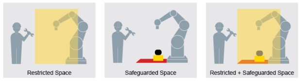
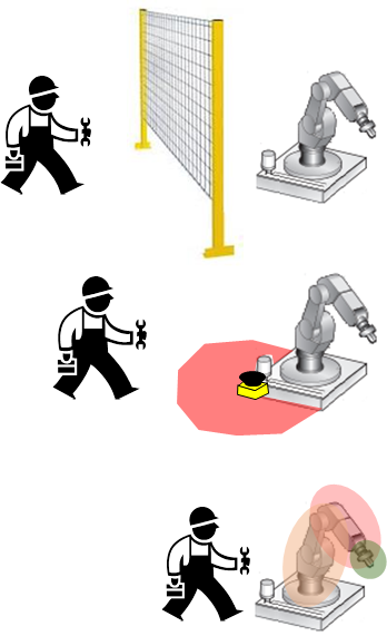
The typical machine/robot guarding scheme of the past used fences or hard guards to separate the human from the machine.  Doors were controlled with safety interlock switches, which required the machine to stop on access, such as to load/unload parts or to perform maintenance or service, and this reduced productivity.  It was also not 100% effective because workers inside a machine area or work cell might not be detected if another worker restarted the stopped machine.  Other drawbacks included the cost of space, guarding, installation, and difficultly changing the work cell layout once hard guarding had been installed.

We’ve now come to an era when our technology and standards allow improved human access to the machine and robot cell.  We’re starting to think about the human working near or even with the machine/robot. The robot and machinery standards have undergone several changes in recent years and now allow new modes of operation.  These have combined with new safety technologies to create a wave of robot and automation suppliers offering new robots, controllers, safety and other accessories.

Standards
Machine and robot safety standards have undergone rapid change in recent years. Standard IEC 61508, and the related machinery standards EN/ISO 13849-1 and EN/IEC 62061, take a functional approach to safety and define new safety performance levels. This means they focus more on the functions needed to reduce each risk and the level of performance required for each function, and less on selection of safety components. These standards helped define, and made it simpler and more beneficial, to apply safety PLCs and advanced safety components. There have also been developments in standards related to safe motion (61800-5-2) which now allow more flexible modes of motion under closely controlled conditions. And the robot standards (10218, ANSI RIA 15.06, TS15066) have made major advances to allow safety-rated soft axes, space limiting and collaborative modes of operation.

Technology
On the technology side, innovations in sensors, controllers and drives have changed the way humans interact with machines and enabled much closer, more coordinated and safer operation. Advanced sensors, such as safety laser scanners and 3D safety cameras, allow creation of work cells with zones, which makes it possible for an operator to be allowed in one zone while the robot performs tasks in a different zone nearby. Controllers now integrate PLC, safety, motion control and other functions, allowing fast and precise control of the process. And drives/motion systems now operate in various modes which can limit speed, torque, direction, etc. in certain modes or if someone is detected nearby.

Sensors and Networks
The monitoring of these robots, machines and “spaces” requires many standard and safety sensors, both inside and outside the machine or robot. But having a lot of sensors does not necessarily allow the shift from “productivity vs. safety” to “productivity & safety” — this requires a closely coordinated and integrated system, including the ability to monitor and link the “restricted space” and “safeguarded space.” This is where field busses and device-level networks can enable tight integration of devices with the control system. IO-Link masters and Safety Over IO-Link hubs allow the connection of a large number of devices to higher level field busses (ProfiNet/ProfiSafe) with effortless device connection using off-the-shelf, non-shielded cables and connectors.

Balluff offers a wide range of solutions for robot and machine monitoring, including a broad safety device portfolio which includes safety light curtains, safety switches, inductive safety sensors, an emergency stop device and a safety hub. Our sensors and networks support the shift to include safety without sacrificing productivity.

To learn more about Safety over IO-Link, visit www.balluff.com

cropped-cmafh-logo-with-tagline-caps.pngCMA/Flodyne/Hydradyne is an authorized  Balluff distributor in Illinois, Wisconsin, Iowa and Northern Indiana.

In addition to distribution, we design and fabricate complete engineered systems, including hydraulic power units, electrical control panels, pneumatic panels & aluminum framing. Our advanced components and system solutions are found in a wide variety of industrial applications such as wind energy, solar energy, process control and more.

How do I justify an IIoT investment?

Guest contributor: Will Healy III, Balluff

Many engineers and managers I meet with when presenting at conferences on Smart Manufacturing ask some version of the question: “How can we justify the extra cost of Industrial Internet of Things (IIoT)?” or “How do I convince management that we need an Industry 4.0 project?” This is absolutely a fair and tough question that needs to be answered; without buy-in from management and proper budget allocation, you can’t move forward. While an investment in IIoT can deliver major payoffs, the best justification really depends on your boss.

I have seen three strong arguments that can be adapted to a variety of management styles and motivations.

1) Showing a ROI through Reducing Downtime

“Show me the money!” I think everyone has a manager with this expectation. It may seem like a daunting task to calculate or capture this information, but by using a team, knowing your KPIs and applying anecdotal feedback, you can get a good initial picture of the ROI that an IIoT project will bring to the organization. Many people have shared with me that their initial project’s ROI has “funded the next project.” There is a really great article from MetalForming Magazine that discusses how exactly to do this with the tables and forms they used at ODM Tool & Manufacturing.

Will1.jpg

2) Corporate Goals for Productivity and Utilization

We can be successful getting support for a project when we link corporate goals to project goals. Smart Industry publishes a research project each year that investigates trends in the manufacturing space in regards to digital transformation initiatives. This report cites that the three top benefits manufacturers are seeing are: improving worker productivity (3rd 2016), reducing costs (1st 2016) and optimizing asset utilization (2nd 2016). These goals are driving investments and showing actual results for manufacturers both large and small. However, the report also revealed that more than half of manufacturers cite workforce skills-gap issues as their largest roadblock and this is, I believe, why we saw improving worker productivity move to the top spot. We must bring efficiency and effectiveness to the people we have.

Will2.png

3) Your Competitors are Investing in IIoT!

If you have a boss that worries about falling behind, this can be a motivating argument. Control Engineering recently published a study of manufacturers and how they are investing in IIoT technologies. The largest investments are coming with sensors, connectivity and data analytics. But what is most shocking is that on average IIoT budgets are $328,160, with 18% budgeting more than a half-million dollars. If you want to keep up with the rapid pace of change in the global market, an investment in IIoT is a requirement to remain competitive.

If you are looking for support and partnership on your IIoT projects, we are experienced at utilizing IO-Link, smart sensors and RFID to enable Industry 4.0 and Smart Manufacturing projects.

cropped-cmafh-logo-with-tagline-caps.pngCMA/Flodyne/Hydradyne is an authorized  Balluff distributor in Illinois, Wisconsin, Iowa and Northern Indiana.

What Exactly is Safety Over IO-Link?

Automation Pyramid.png

This integrated safety concept is the logical continuation of the IO-Link philosophy. It is the only globally available technology to build on the proven IO-Link standards and profisafe. This means it uses the essential IO-Link benefits such as simple data transport and information exchange, high flexibility and universal applicability for safety signals as well. Safety over IO-Link combines automation and safety and represents efficient safety concepts in one system. Best of all, the functionality of the overall system remains unchanged. Safety is provided nearly as an add-on.

In the center of this safety concept is the new safety hub, which is connected to an available port on an IO-Link master. The safety components are connected to it using M12 standard cable. The safety profisafe signals are then tunneled to the controller through an IO-Link master. This has the advantage of allowing existing infrastructure to still be used without any changes. Parameters are configured centrally through the user interface of the controller.

Safety Hub

The safety hub has four 2-channel safe inputs for collecting safety signals, two safe outputs for turning off safety actuators, and two multi-channel ports for connecting things like safety interlocks which require both input and output signals to be processed simultaneously. The system is TÜV- and PNO-certified and can be used up to PLe/SIL 3. Safety components from all manufacturers can be connected to the safe I/O module.

Like IO-Link in general, Safety over IO-Link is characterized by simple system construction, time-and cost-saving wiring using M12 connectors, reduction in control cabinet volume and leaner system concepts. Virtually any network topology can be simply scaled with Safety over IO-Link, whereby the relative share of automation and safety can be varied as desired. Safety over IO-Link also means unlimited flexibility. Thanks to varying port configuration and simple configuration systems, it can be changed even at the last minute. All of this helps reduce costs. Additional savings come from the simple duplication of (PLC-) projects, prewiring of machine segments and short downtimes made possible by ease of component replacement.

Development of IO-Link, number of sold nodes.png

To learn more about Safety over IO-Link, visit www.balluff.com

cropped-cmafh-logo-with-tagline-caps.pngCMA/Flodyne/Hydradyne is an authorized  Balluff distributor in Illinois, Wisconsin, Iowa and Northern Indiana.

In addition to distribution, we design and fabricate complete engineered systems, including hydraulic power units, electrical control panels, pneumatic panels & aluminum framing. Our advanced components and system solutions are found in a wide variety of industrial applications such as wind energy, solar energy, process control and more.

When and Where to Use Continuous Cylinder Position Sensing

The role of smart cylinders — hydraulic or pneumatic cylinders with integrated position detection capability — has increased as manufacturers constantly strive to improve efficiency through automation. Smart cylinders can use either continuous or discrete position sensing, providing manufacturers with options, but possibly leaving them with questions on which is best for their application.

In this post we will review the benefits of continuous position sensors and list the applications where this is the best fit.

Continuous position sensors provide near real-time position feedback throughout the entire stroke of the cylinder making them the ideal choice for applications at the higher end of the control spectrum. Closed-loop servohydraulic systems can achieve sophisticated, dynamic control of motion across the entire cylinder stroke.

Continuous position sensors are commonly used when the application calls for closed-loop servo control, where the position, speed, acceleration, and deceleration of the cylinder must be controlled. Closed-loop servohydraulics have been widely used in industrial applications, such as sawmills, steel processing and tire manufacturing, and more recently in cylinders in off-highway equipment.

Magnetostrictive linear position sensors are the most commonly used continuous position sensors in hydraulic cylinders. These sensors are installed into the back end of the cylinder. The sensor detects the position of a magnet attached to the piston and provides a continuous, absolute position signal.

Blog
Magnetostrictive linear position sensor installed in hydraulic cylinder

The sensor is rated to withstand the full pressure of the hydraulic system. Magnetostrictive technology offers the advantage of being completely non-contact, meaning it requires no mechanical contact between the sensor and the moving cylinder and is not subject to wear and performance degradation. In addition, numerous electrical interface options are available, from simple analog (0 to 10V or 4-20mA) to high-performance industrial fieldbus interfaces that offer advanced functionality.

Continuous position sensors can also be used in pneumatic cylinders. While closed-loop servo control with pneumatics is not as common as it is with hydraulics, there are situations where pneumatic cylinders require continuous position sensing capability. For example, low-pressure pneumatic cylinders are sometimes used as measurement probes, or touch probes, where the cylinder rod is extended until it touches a part to be measured or gaged. In these situations, it is beneficial to be able to get continuous position feedback, especially when there is variability in the measured part.

To learn more about cylinder position sensing, visit www.balluff.com.

cropped-cmafh-logo-with-tagline-caps.pngCMA/Flodyne/Hydradyne is an authorized  Balluff distributor in Illinois, Wisconsin, Iowa and Northern Indiana.

In addition to distribution, we design and fabricate complete engineered systems, including hydraulic power units, electrical control panels, pneumatic panels & aluminum framing. Our advanced components and system solutions are found in a wide variety of industrial applications such as wind energy, solar energy, process control and more.

A Smarter SmartLight

Guest contributor: Tom Rosenberg, Balluff

Just when you thought the SmartLight was the most flexible Tower Indicator light ever, it gets even more flexible with the addition of a new mode. This new mode is appropriately named “Flexible Mode”. The new Flexible mode enables two new applications: User defined segments and Point-of-use indication.

User Defined Segments

For traditional tower light applications, it’s now Figure 1
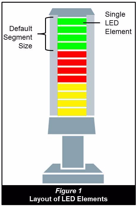
possible to define the segments as you see fit. It works by taking control of every LED element. Each SmartLight segment is comprised of four LED elements that can be controlled anyway you want (see Figure 1).  For example, with the 3-segment SmartLight, you actually have 12 LED elements that you can organize any way you want. In Figure 2, we only use three LED elements per SmartLight segment, making it a four segment SmartLight. By using two LED elements we create six segments. Figure 3 is even more interesting, in this example we can see the size of the segments are sized by the intended users. Forklift Drivers need a larger light due to the distance and the fact that they are moving. Operators are closer than the forklift drivers, so their segment can be smaller, and maintenance can use the smallest segments because they are closest to the SmartLight when working on the machine.

Point of Use Indication

In these types of applications, the SmartLight is usedSocket Tray Appin close proximity, usually within the work envelope of the operators. In the example shown, the SmartLight is used in a socket tray application. The SmartLight indicates to the operator which socket is required for a specific task. Inductive proximity sensors connected to an IO-Link Hub verify the correct socket was pulled. The photo is showing an All-Call (all lights lit). Here you can see the unique LED element grouping only available with the new Flexible mode. Other applications for operator guidance are essentially endless. There are no technical limitations to your creativity.

The Flexible mode is available in all SmartLights with firmware version 3.0 or greater. So go have some fun!

Learn more about the SmartLight at www.balluff.com.

cropped-cmafh-logo-with-tagline-caps.pngCMA/Flodyne/Hydradyne is an authorized  Balluff distributor in Illinois, Wisconsin, Iowa and Northern Indiana.

In addition to distribution, we design and fabricate complete engineered systems, including hydraulic power units, electrical control panels, pneumatic panels & aluminum framing. Our advanced components and system solutions are found in a wide variety of industrial applications such as wind energy, solar energy, process control and more.

Increase Competitiveness with RFID in the Intralogistics Industry

Guest contributor: Nadine Brandstetter, Balluff

In times of globalization and high labor costs it is a challenge to increase competitiveness in the fashion industry. Within a warehouse, an RFID system supports a high degree of automation as well as short transport distances. To supply dealers and to keep their facility profitable, one of the most successful fashion companies in the world has built a highly modern hanging garment distribution center. Let’s take a look at how they successfully implemented RFID technology to improve their processes.

Separate and sort clothes with just one hybrid module (2D code + RFID)

Within this distribution center 45,000 of these innovative clothes hanger adapters (L-VIS) are used. They replace the previous trolley-based logistics approach by allowing the transportation of a number of different garments that have the same destination.

OLYMPUS DIGITAL CAMERA

With the investment in some additional space in the so-called buffer or storage zone, and by providing empty trolleys at various locations to keep the product flow moving, this project is successfully accomplished. A major advantage of this system, is the usability over the entire intralogistics chain. From receiving, to the hanging storage, to the sorter for single item identification, and from there as a transport unit to shipping.

The clothes hanger contains an RFID chip, that is automatically read by the conveying technology, and the 2D-code. This code is read manually by employees with a portable acquisition unit. The code can be DMC (Data Matrix Code), QR-Code, or any other optical code standard.

OLYMPUS DIGITAL CAMERA

Information exchange without visual contact

An RFID chip from the Balluff BIS-M series is installed. With this identification system, neither direct alignment nor contact is needed to enable data exchange via nearfield communication. Non-contact identification is extremely reliable and wear-free. The identification system consists of a rugged data carrier, a read/write head and an RFID processor unit. The processor unit communicates to the control system via Profibus. Other options available include ProfiNet, Ethernet-IP, etc.

OLYMPUS DIGITAL CAMERA

The following table gives you an overview of which Radio Frequency Identification solutions are available at Balluff:

LF (BIS C) LF (BIS L) HF (BIS M) UHF (BIS U)
Frequency 70/455 kHz 125 kHz 13.56 MHz 860 … 960 MHz
Short description Dedicated solution to tool identification in Metal-Working industry. Standard solutions for simple Track & Trace applications. Fast & reliable – even with high volumes of data in medium distances in assembly, production and intralogistics. Identification at large distances and bunching capability for current material flow concept.

Learn more about Balluff solutions here.

For the customer, the decision to choose Balluff’s BIS-M system among others was the separation between the processor and read/write head. In a widespread facility it would not make sense to have a decoder with 30 read/write heads attached. By interfacing two read/write heads per processor it is possible to track the travel of a transport unit over the entire conveyor line as well as track within the aisles between the individual shelves. With the new BIS-V generation of RFID processors, even 4 read/write heads per processor can be connected.

Convincing product and support

An additional advantage of the BIS system is the compactness of its electronics. The L-VIS and the 30 mm read/write head are an ideal match. The simple mounting of the processors and ready-to-use connection persuaded the system integrators, in addition to the fact that the technology was already perfected and operated flawlessly. In the sorting area, the 2D code was supplemented by the RFID tags to reach speeds of up to 0.6 and 0.7 m/s. This would probably not have been possible with the installation of a corresponding camera technology.

Experiences have shown, that RFID projects need a lot of support. Consultation and assistance from true experts can be provided by the Balluff team. Get to know Balluff at www.balluff.com

cropped-cmafh-logo-with-tagline-caps.pngCMA/Flodyne/Hydradyne is an authorized  Balluff distributor in Illinois, Wisconsin, Iowa and Northern Indiana.

In addition to distribution, we design and fabricate complete engineered systems, including hydraulic power units, electrical control panels, pneumatic panels & aluminum framing. Our advanced components and system solutions are found in a wide variety of industrial applications such as wind energy, solar energy, process control and more.

Back to the Basics: What is the Value of IO-Link?

Guest Contributor: Will Healy III, Balluff

IO-Link

With the demands for flexible manufacturing, efficient production & visibility in our factories, smart manufacturing is driving the way we work today.  Analytics and diagnostics are becoming critical to our ability to perform predictive maintenance, improve equipment effectiveness and monitor the condition of the machine as well as the components inside the machine.  Typically, our first reaction is to put these devices onto Ethernet.  However, the implementation of Ethernet requires a high skill set that is scarce in our traditional manufacturers today.  Due to the simple control architecture of IO-Link devices, it allows for many Smart devices to provide the data we need for analytics with a reduction in the Ethernet skill set that has become a roadblock for many manufacturers.

Many people think IO-Link is a new industrial network to compete with EtherNet/IP or Profinet, but this is a common misconception. IO-Link is complementary to those networks and typically enables those networks to do even more than previously thought.

Standard IO-Link Setup_01_preview

Open Standard

IO-Link is an open standard designed with the idea to act like USB for industrial automation.  IO-Link is meant to simplify the smart sensor & intelligent device connectivity on the factory floor in a similar way that USB simplified connectivity to computers for auxiliary devices.  IO-Link is not an industrial network or fieldbus; it is an industrial network and industrial controller agnostic. Designed with a master to slave configuration, addressing of the devices is point-to-point, similar to USB.  Compatible IO-Link masters can act as slaves or nodes on a variety of industrial protocols and act complementary to the network of the user’s choosing.  Eliminating the need for serial communication configuration or network addressing simplifies the connection and integration of devices.

Value in Machine Builds

IO-Link has advantages for both machine io-link master_18x18_300dpibuilders and discrete manufacturers.  For machine builders, the biggest advantage comes from the simplified wiring scheme of IO-Link devices.  We have seen machine builder users of IO-Link reduce their wiring hardware & labor costs by 30%-60% for sensors,
outputs & controls.  This is realized with the simple sensor tool cords used for connections, quick-disconnect connectors on the cables and machine mount Ethernet masters devices.  It is also realized for machine builders in an increase of turns on their floor, a reduction in build labor and significantly faster commissioning time.

Value on the Production Floor

For discrete manufacturers, the biggest advantages have come from the parameterization and diagnostic features on the IO-Link devices.  With the ability to store & send parameters between the master & slave, IO-Link devices can be automatically configured. Hot-swapping a complex smart device like a pressure sensor can go from a stressful ordeal including 14-plus setpoints to literally a push of one button.  Combining this functionality with multiple diagnostics both in the master & slaves eliminates human error and dramatically reduces downtime & troubleshooting for manufacturers.

To learn more about market leading IO-Link technologies, visit www.balluff.com.

cropped-cmafh-logo-with-tagline-caps.pngCMA/Flodyne/Hydradyne is an authorized  Balluff distributor in Illinois, Wisconsin, Iowa and Northern Indiana.

In addition to distribution, we design and fabricate complete engineered systems, including hydraulic power units, electrical control panels, pneumatic panels & aluminum framing. Our advanced components and system solutions are found in a wide variety of industrial applications such as wind energy, solar energy, process control and more.