In industrial distance and position measurement applications, one size definitely does not fit all. Depending on the application, the position or distance to be measured can range from just a few millimeters up to dozens of meters. No single industrial sensor technology is capable of meeting these diverse requirements.
Fortunately, machine builders, OEM’s and end-users can now choose from a wide variety of IO-Link distance and position measurement sensors to suit nearly any requirement. In this article, we’ll do a quick rundown of some of the more popular IO-Link measurement sensor types.
(For more information about the advantages of IO-Link versus traditional analog measurement sensors, see the following blog posts, Solving Analog Integration Conundrum, Simplify Your Existing Analog Sensor Connection, and How Do I Make My Analog Sensor Less Complex?)
Short Range Inductive Distance Sensors
These sensors, available in tubular and block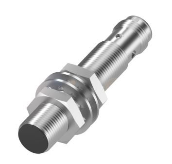 style form factors are used to measure very short distances, typically in the 1…5 mm range. The operating principle is similar to a standard on/off inductive proximity sensor. However, instead of discrete on/off operation, the distance from the face of the sensor to a steel target is expressed as a continuously variable value. Their extremely small size makes them ideal for applications in confined spaces.
Inductive Linear Position Sensors
Inductive linear position sensors are available in several block style form factors, and are used for position measurement over stroke lengths up to about 135 mm. These types of sensors use an array of inductive coils to accurately measure the position of a metal target. Compact form factors and low stroke-to-overall length factor make them well suited for application with limited space.


Magnetostrictive Linear Position Sensors
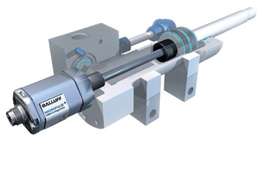
IO-Link Magnetostrictive linear position sensors are available in rod style form factors for hydraulic cylinder position feedback, and in external mount profile form factors for general factory automation position monitoring applications. These sensors use time-proven, non-contact magnetostrictive technology to provide accurate, absolute position feedback over stroke lengths up to 4.8 meters.


Laser Optical Distance Sensors
 Laser distance sensors use either a time-of-flight measuring principle (for long range) or triangulation measuring principle (for shorter range) to precisely measure sensor to target distance from up to 6 meters away. Laser distance sensors are especially useful in applications where the sensor must be located away from the target to be measured.
Magnetic Linear Encoders
IO-Link magnetic linear encoders use an absolute-coded flexible magnet tape and a compact sensing head to provide extremely accurate position, absolute position feedback over stroke lengths up to 8 meters. Flexible installation, compact overall size, and extremely fast response time make magnetic linear encoders an excellent choice for demanding, fast moving applications.
IO-Link Measurement Sensor Trends
The proliferation of available IO-Link measurement sensors is made possible, in large part, due to the implementation of IO-Link specification 1.1, which allows faster data transmission and parameter server functionality. The higher data transfer speed is especially important for measurement sensors because continuous distance or position values require much more data compared to discrete on/off data. The server parameter function allows device settings to be stored in the sensor and backed up in the IO-Link master. That means that a sensor can be replaced, and all relevant settings can be downloaded from master to sensor automatically.
To learn about IO-Link in general and IO-Link measurement sensors in particular, visit www.balluff.com.
![]() CMA/Flodyne/Hydradyne is an authorized Balluff distributor in Illinois, Wisconsin, Iowa and Northern Indiana.
CMA/Flodyne/Hydradyne is an authorized Balluff distributor in Illinois, Wisconsin, Iowa and Northern Indiana.
In addition to distribution, we design and fabricate complete engineered systems, including hydraulic power units, electrical control panels, pneumatic panels & aluminum framing. Our advanced components and system solutions are found in a wide variety of industrial applications such as wind energy, solar energy, process control and more.
 extending the full length of the mechanical stroke. A magnet ring is used as a position marker and mounted on the face of the piston. As the piston (and the position marker) move, the linear position sensor provides a continuous absolute position by way of an analog or digital signal.