hydraulic valves

Hydraulic Valves Will Benefit From Connectivity

Guest contributor, Jeroen Brands, Bosch Rexroth

Hydraulic valves: Directional valve with integrated digital axis controller

Hydraulic valves: Directional valve with integrated digital axis controller

What are the current market requirements for hydraulic valves?

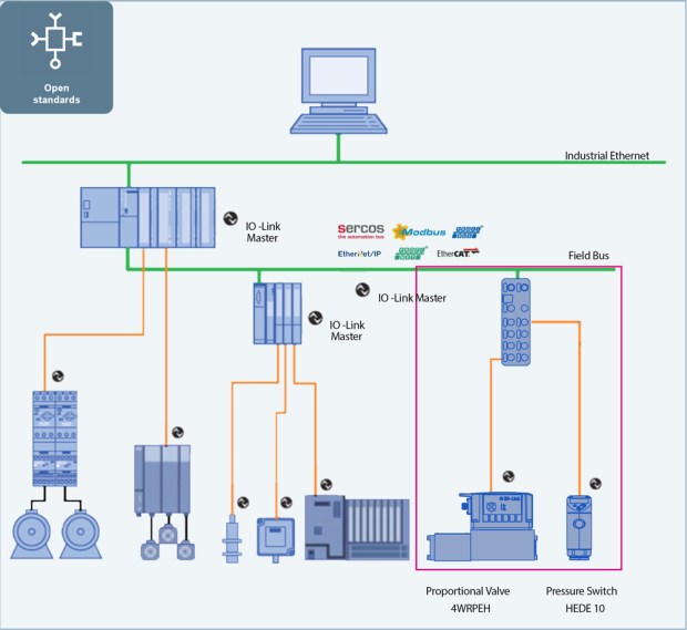
We are currently experiencing a transition from classic, analogous hydraulics to connectable digital fluid technology. European machine manufacturers in particular are increasingly digitizing their machine designs and expect that hydraulics can be seamlessly embedded into these connected environments. This means that regarding the level of automation, hydraulics are on a par with electromechanical drives. One of the decisive features in this respect is the seamless integration of intelligent hydraulic valves into different automation topologies via open standards such as multiple Ethernet interfaces.

Which new technical possibilities are available to meet these requirements?

Smart single-axis controllers are already remotely regulating hydraulic motions in a closed control loop. In addition, a powerful motion control is integrated into the on-board electronics of the valve. It performs the target-actual comparison on site and regulates accurately to a few micrometers. The control quality of the system is exclusively determined by the resolution of the measurement systems. These motion controls without control cabinet are increasingly used in saw lines, paper mills and machine tools. In addition, there are smart variable speed pump drives and smart pump controls. They provide completely new possibilities of replacing the throttle controls, which were predominantly used up to now, by more energy-efficient displacement controls. In this way, functions which were previously executed by valves are relocated to the software.

What about the integration of sensor technology into hydraulic valves?

The mass production of sensors for the automotive or the consumer products industry has significantly reduced the costs. Now, sensors are increasingly used in hydraulics. In our opinion, the integration of sensor technology of this kind into existing valve housings is the next step. Regarding condition monitoring, sensors could collect information on fluid quality, temperature, vibrations and performed switching cycles. Via deep learning algorithms, users can then detect wear before it causes malfunction.

Which other possibilities of mechanization does a valve provide?

The degree of freedom regarding connection geometries is already limited by standard requirements. The hydraulics industry discussed the topic of digital hydraulics in great depth some time ago. The idea was and is to control flows in a “stepped” or “clocked” way using single- or multi-bit strategies. In certain applications, this can constitute an advantage compared to continuously variable technology.

Which other innovations in hydraulic valves are relevant in your company?

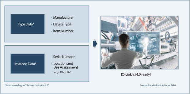
It is no longer a question whether hydraulic valve technology will benefit from connectivity or not. The only question is when. The current discussions around Industry 4.0 clearly show how important it is to define all required functions and functionalities. Only if mechanisms and sensor technology are standardized across different manufacturers will active connectivity and communication be possible. Even in the future, not every hydraulic-mechanical pressure valve will have digital electronics on board or be connected to a control system or other valves. An imprinted QR code with information on the manufacturer’s settings, functional descriptions or information on replacement seals are a first step towards connectivity. In the area of new materials and production technologies, Rexroth has many innovations in the pipeline. 3D printing of cores for cast housings or direct printing considerably lowers energy consumption during the operation of valves. While the divisibility of the core mold had to be taken into account in the design of the core, this is no longer necessary today thanks to core printing. This means that we can use other channel designs which allow for lower pressure losses and improve energy consumption. For a valve with a flow of 10,000 l/min, the reduction of flow resistance by 10 to 20 percent significantly reduces the operating expenses.

Pressure transducer for hydraulic applications

How do these trends affect your products?

With the IAC (integrated axis controller) valves, Bosch Rexroth offers motion control without control cabinet which is completely integrated into valve electronics. It can be fully connected via open interfaces. The same applies to servo-hydraulic axes with their own fluid circuit. In these ready-to-mount axes, pump, valves and cylinders form an assembly to which the machine manufacturer only has to connect power supply and control communication. They use the same commissioning tools and user interfaces which means that all drive technologies provide the same look and feel. Classic servo valves, however, can also be improved further. New plug-in amplifiers with pulse width modulation for on/off valves by Rexroth reduce the surface temperature of the connectors by more than 80 degrees to only 50 degrees. This is particularly interesting for saw lines where easily inflammable sawdust constitutes an explosion hazard.

Outlook: How will valve technology change in the next 10 years?

In 10 years, valves will allow for easier project planning, more comfortable commissioning and more efficient operation and will provide more information before a service case. If service is required, the valve may already have ordered its spare parts.


cropped-cmafh-logo-with-tagline-caps.pngCMA/Flodyne/Hydradyne is an authorized Bosch Rexroth distributor in Illinois, Wisconsin, Iowa and Northern Indiana.

In addition to distribution, we design and fabricate complete engineered systems, including hydraulic power units, electrical control panels, pneumatic panels & aluminum framing. Our advanced components and system solutions are found in a wide variety of industrial applications such as wind energy, solar energy, process control and more.

Hydraulics with IO-Link: Reduced effort, high value

Guest contributor: Theobald Herrmann, Bosch Rexroth

In almost all industries, machine users require increased flexibility for production means for small batches and continuous diagnostics of all actuators and sensors to increase availability. In addition to this, there is quickly increasing horizontal and vertical connection of machinery and systems for Industry 4.0 applications. The open standard IEC 61131-9, IO-Link, fulfills these requirements at low connection costs and energy consumption. Flexibility of hydraulics is increased by transmission of parameter changes in running operation. Provision of diagnostics information offers numerous opportunities to extend the concepts of predictive maintenance to increase availability of the systems. The manufacturer-independent IO-Link can be integrated easily and quickly in any industrial automation application.

Standardized wiring and electronic name plate support commissioning and increase availability

• Open standard for bi-directional point-to-point connections in parallel to field bus
• Easy connection with standard cables and M12 connectors
• No additional engineering tool necessary, possible configuration via control system.
• Data for predictive maintenance and quick device replacement
 Industry 4.0-compatible hydraulic components for vertical flow of information

Introduction: Limits of serial field bus communication

The introduction of field bus technology in the 1980s was the starting point for horizontal connection of decentralized actuators within machinery. Serial wiring lead to a considerable reduction in cabling and opened new possibilities for modularization in mechanical engineering. Field buses as well as most current real-time Ethernet protocols are manufacturer-specific, proprietary systems. The protocols have been developed by control system manufacturers and focus on communication between own electric control systems and selected peripherals. For actuators, sensors and other third-party equipment, either their manufacturers or system integrators are required to provide suitable interfaces in hardware and software for the respective field bus. This is very complex as device profiles and software have to be created in the respective PLC for every individual field bus and control system of each manufacturer.

Possibilities for hydraulic connection

Integration of hydraulics in modern automation systems can be realized in different ways. Numerous existing machine concepts apply on-board electronics for control of hydraulic valves. Exchange of digital information is restricted and only possible if the respective device is connected to a superior control system via individual wiring. This state-of-the-art in technology increasingly no longer meets the requirements of end users.

The alternative are valves with integrated field bus connection. These, however, require extensive wiring as well as integration into the control system and the respective field bus protocol by means of dedicated software. Both requires considerable effort that is too high particularly for price-sensitive applications.

Thanks to IO-Link, machine manufacturer and system integrators are enabled to integrate for example proportional hydraulic series valves and sensors into digital communication structures with very little engineering effort. With its simple communication structure, IO-Link has low hardware requirements. Additionally, the standardized M12 connection technology enables simple and cost-efficient connection of hydraulic valves in the field. This way, previously “deaf-mute” components with analog control are transformed in communicating and flexible actuators and sensors.

IO-Link: Manufacturer-independent and compatible with all field bus protocols

The manufacturer-independent IO-Link according to IEC 61131-9 standardizes connection technology for actuators, sensors and other equipment and provides a digital communication protocol for data exchange between control systems and devices regardless of the field bus. Field bus technology is not replaced but extended. Parallel communication enables machine manufacturers use of IO-Link with all protocols and integration of IO-Link-compatible devices into various concepts without additional effort.

IO-Link is currently already supported by around 130 device manufacturers and companies in the field of technology. Around 40 manufacturers offer IO-Link Masters and the standard is supported by nine manufacturers of control systems with central Masters and respective engineering tools. IO-Link devices are in the product range of almost sixty manufacturers of sensors, actuators and other peripherals. Rexroth, for example, now also offers hydraulic proportional valves and pressure sensors with respective technology. Function and performance of these proportional valves are identical to series valves. However, they also offer all options for bi-directional communication via IO-Link. This way, the hydraulics can be integrated seamlessly into connected structures. Parameters can be changed and operating states changed by the control system during running operation.

IO-Link system set-up

A full IO-Link system consists of one centralized or decentralized IO-Link Master, one or more IO-Link devices as well as unshielded 3 or 5-conductor standard cables with M12 connectors. Project planning and parameterization of the IO-Link Master can be realized in the control system hardware or an optional engineering tool. The point-to-point connections between IO devices and the automation system are established by the Master. It serves as the interface to the superior control system.

bild01_offenestandards_en

IO-Link Masters are offered by around 50 manufacturers for connection of one IO device per port. The selection includes options for the IP20 control cabinet as well as decentralized modules with protection class IP65/67 for installation at machinery. Particularly in large-scale systems, cabling is considerably reduced.

For decentralized IO-Link Masters, the user organization of IO-Link has defined M12 plug-in connectors with three or five conductors. The 5-pole version “Class B” port is used for devices with increased current consumption like hydraulic valves. The 3-pole version “Class A” port provides an energy supply of up to 200 mA which is sufficient for most sensors. In contrast to analog controls, unshielded cables are sufficient for fault-free communication over a cable length of up to 20 meters. IO-Link standardizes connection technology for all actuators and sensors and eliminates numerous sources of errors during the installation of systems. Otherwise complicated and expensive cable dimensioning with individual wiring and shielding is no longer required. In addition, the logistic effort is reduced thanks to application of uniform M12 cables for sensors and actuators.

Rapid commissioning per software

Every IO-Link device features an electronic device description, referred to as IO Device Description (IODD). It provides standardized important information:

• Device data
• Text description
• Identification, process and diagnosis data
• Communication properties
• Device parameters with value range and default value.
• Image of the device
• Logo of the manufacturer

The IODD set-up is identical for all devices of all manufacturers. The IODD enables automatic recognition of the device by the IO-Link Master for immediate parameterization. Also automatically, device descriptions are included in the system documentation.

For project integration of the IO-Link Master in overall automation, commissioning personnel use the engineering tools of the respective PLC manufacturer. The IO-Link Master is selected from the device portfolio and added to overall automation. Depending on the control system manufacturer, all blocks for communication are available in a library for free.

bild02_io_link_en

Via IO-Link to Industry 4.0

IO-Link enables access to device data either directly from the control system or remotely via networks from any location. Particularly important for future-oriented concepts: Already today, IO-Link offers type and instance data of Industry 4.0 devices according to the definition of the German “Plattform Industrie 4.0” initiative.

This way, also hydraulic actuators meet all conditions for future requirements of Industry 4.0 applications. Additionally, this approach is well-suited for subsequent connection of existing machinery and systems with low effort. Users replace installed proportional valves and sensors by interchangeable options with IO-Link connection for direct communication with actuators and sensors.

Diagnosis functions for increased availability

The diagnosis functions of IO-Link devices enable new maintenance concepts and considerably reduce repair times. Now possible call-up of device information in parallel to the process forms the basis for condition-oriented and predictive maintenance concepts. In this respect, proportional valves report whether they are functional as well as errors like under or overvoltage. In addition, the valve and sensor status is displayed for transparent error analysis. An integrated operating hour indicator enables calculation of the residual life-cycle for maintenance and decision-making on further use of the valve.

In case of faults, IO-Link accelerates diagnosis thanks to remote access for maintenance specialists to identify the type and location of any errors. Precise localization without personal presence at the system alone considerably reduces reaction times. If necessary, the maintenance technician opens the IODD file of the respective device in the control system. Other than before, components do not need to be disassembled to decipher hardly readable labels and manufacturers and types no longer need to be looked for in system documentations. Thanks to the electronic name plate, all this information can now be accessed with just one mouse click to initiate the respective order without delay.

IO-Link follows the plug & play principle. Replaced devices are recognized by the IO-Link Master according to their IODD file and the respective parameters are automatically transferred without any actions in the software. This way, even less experienced technicians are enabled to replace components without problems to considerably reduce system downtimes.

Summary

The open IO-Link standard establishes continuous communication with sensors and actuators irrespective of the used field bus. Now, even hydraulic proportional valves can be intelligently, easily and cost-effectively integrated in bi-directional digital communication. This simplifies commissioning in hardware and software and enables flexible adjustment of hydraulic valves for varying production processes. Increased requirements for flexible machinery and systems are now complied with. Extended diagnosis information enables condition-oriented and predictive maintenance concepts and standstill and maintenance times are reduced. This increases the availability of machinery. In addition, IO-Link enables future-proof integration of hydraulic valves into connected structures as Industry 4.0 components with all their related features.

Why hydraulics and IO-Link? Click here

Learn more about Rexroth and IO-Link

cropped-cmafh-logo-with-tagline-caps.pngCMA/Flodyne/Hydradyne is an authorized Bosch Rexroth distributor in Illinois, Wisconsin, Iowa and Northern Indiana.

In addition to distribution, we design and fabricate complete engineered systems, including hydraulic power units, electrical control panels, pneumatic panels & aluminum framing. Our advanced components and system solutions are found in a wide variety of industrial applications such as wind energy, solar energy, process control and more.


Hydraulic Valves – Customize your Feedback

Guest contributor: Chris Heberlein, Balluff

Hydraulic actuators can be used to open and close a valve’s position.  In automation architectures, a linear position sensor is used within the hydraulic actuator to provide continuous position feedback.

The linear position sensor is installed into the back end of the cylinder.  The sensing element resides in a cavity that has been gun-drilled through the piston and cylinder rod, Image1
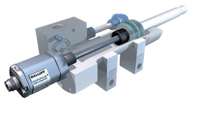
extending the full length of the mechanical stroke. A magnet ring is used as a position marker and mounted on the face of the piston.  As the piston (and the position marker) move, the linear position sensor provides a continuous absolute position by way of an analog or digital signal.

In some applications, a cylinder’s position may only be moving across a small portion of the overall stroke or a specific portion of the stroke.  The end user could benefit from altering the transducer’s signal based on the application’s specific stroke requirements instead of the entire cylinder’s stroke, thereby maximizing available position resolution.  When this situation arises, most transducer manufacturers offer the ability to customize or “teach” a modified output of the stroke via push buttons or from wiring inputs.  When this is done, the process does require the cylinder (and position marker) to move to these defined locations for a “teach”.

Image2

A more user-friendly and repeatable approach for customized stroke lengths with linear position sensors is to use a graphical software package. The software can be connected
from a PC via USB to a compatible linear position sensor. Starting and ending stroke values can be precisely entered into the software and a graphical representation of the output curve is created.  For a more straightforward approach, you can also drag and drop these stroke points by a click of a cursor. The file can be saved on a PC and downloaded to the transducer. In either case, the cylinder’s piston doesn’t need to be actuated.

Image3

In projects where multiple, identical actuators and linear position sensors need to be customized, the setup would only need to be done once, the file saved, and simply uploaded to all the sensors for the project.  A great time-saver over manually teaching each and every sensor.

Another benefit to using software with linear position sensors is to be able to upload programs for replacement units in a safe user environment (e.g. lab station or office) and shipping them to various job sites.  These different locations (or locales) can be in harsh environmental conditions (extreme cold or heat) or areas that contain ignitable or explosive gases or dusts which may be difficult to work in.

Image4

Other software features include inverting the output curves, offering position or velocity outputs, and more.

For more information on Balluff’s Magnetostrictive Linear Position Sensors, visit www.balluff.com.

cropped-cmafh-logo-with-tagline-caps.pngCMA/Flodyne/Hydradyne is an authorized  Balluff distributor in Illinois, Wisconsin, Iowa and Northern Indiana.

In addition to distribution, we design and fabricate complete engineered systems, including hydraulic power units, electrical control panels, pneumatic panels & aluminum framing. Our advanced components and system solutions are found in a wide variety of industrial applications such as wind energy, solar energy, process control and more.