Sensors

Reliable Part Exit/Part-Out Detection

Guest contributor: Dave Bird, Balluff

Walk into any die shop in the US and nine out of ten times, we discover diffuse reflective sensors being used to detect a large part or a small part exiting a die. Many people have success using this methodology, but lubrication-covered tumbling parts can create challenges for diffuse-reflective photoelectric sensing devices for many reasons:

  1. Tumbling parts with many “openings” on the part itself can cause a miss-detected component.
  2. Overly-reflective parts can false triggering of the output.
  3. Dark segments of the exiting part can cause light absorption. Remember, a diffuse sensors sensing distance is based on reflectivity. Black or dark targets tend to absorb light and not reflect light back to the receiver.
  4. Die lube/misting can often fog over a photoelectric lens requiring maintenance or machine down time.

The solution: Super Long Range Inductive Sensors placed under chutes

Most metal forming personnel are very familiar with smaller versions of inductive proximity sensors in tubular sizes ranging from 3mm through 30mm in diameter and with square or “block style” inductive types (flat packs, “pancake types”, etc.) but it is surprising how many people are just now discovering “Super Long Range Inductive Proximity” types. Super Long Range Inductive Proximity Sensors have been used in metal detection applications for many years including Body-In-White Automotive applications, various segments of steel processing and manufacturing, the canning industry, and conveyance.

Benefits of Using A UHMW Chute + Super Long Range Inductive Proximity Sensor in Part Exit/Part-Out Applications:

  1. It is stronger and quieter than parts flowing over a metal chute, readily available in standard and custom widths, lengths and thicknesses to fit the needs of large and small part stampers everywhere.
  2. UHMW is reported to be 3X stronger than carbon steel.
  3. UHMW is resistant to die lubes.
  4. UHMW allows Super Long Range Inductive Proximity Sensors to be placed underneath and to be “tuned” to fit the exact zone dimension required to detect any part exiting the die (fixed ranges and tunable with a potentiometer). The sensing device is also always out of harm’s way.
  5. Provides an option for part detection in exiting applications that eliminates potential problems experienced in certain metal forming applications where photoelectric sensing solutions aren’t performing optimally.

A Two-Out Die with Metallic Chute

Not every Part Exit/Part-Out application is the same and not every die, stamping application, vintage of equipment, budget for sensing programs are the same. Butit’s important to remember in the world of stamping, to try as consistently as possible to think application specificity when using sensors.  That is, putting the right sensing system in the right place to get the job done and to have as many technical options available as possible to solve application needs in your own “real world” metal forming operation.  We believe the UHMW + Super Long Range Inductive System is such an option.

You can learn more in the video below or by visiting www.balluff.us.


cropped-cmafh-logo-with-tagline-caps.pngCMA/Flodyne/Hydradyne is an authorized  Balluff distributor in Illinois, Wisconsin, Iowa and Northern Indiana.

In addition to distribution, we design and fabricate complete engineered systems, including hydraulic power units, electrical control panels, pneumatic panels & aluminum framing. Our advanced components and system solutions are found in a wide variety of industrial applications such as wind energy, solar energy, process control and more.

3 Tips for Reducing Downtime

Guest contributor:  Janet Czubek, Balluff

Whether it’s through preventative maintenance or during planned machine downtime, reducing downtime is a common goal for manufacturers. Difficult environments create challenges for not just machines, but also the components like sensors or cables. Below are three tips to help protect these components and reduce your downtime.

sacraficialcableCables don’t last forever. However, they are important for operations and keeping them functional is vital. An easy way to help reduce downtime and save money is by implementing a “sacrificial cable” in unforgiving environments. A sacrificial cable is any cable less than two meters in length and placed in situations where there is high turnover of cables.  This sacrificial cable does not have to be a specialty cable with a custom jacket. It can be a simple 1 meter PVC cable that will get changed out often. The idea is to place a sacrificial cable in a problematic area and connect it to a longer length cable, or a home-run cable. The benefits of this method include: less downtime for maintenance when changing out failures, reduced expenses since shorter cables are less expensive, and there is less travel for the cable around a cell.

hdc_cablesA second way to help reduce downtime is consider your application conditions up front. We discussed some of the application conditions to consider in a previous blog post, but how can we address these challenges? Not only is it important to choose the correct sensor for the environment, but remember, cables don’t last forever. Choosing the appropriate cable is also key to reducing downtime. Welding environments demand a cable that weld beads will not stick to and fuse the cable to the sensor. There are a variety of jacket types like silicone, silicone tube, or PTFE that prevent weld debris from accumulating on the cable. I’ve also seen applications where there is a lot of debris cutting through cables. In this case, a stainless steel braid cable would be a better solution than a traditional cable. Fitting the right protection to the right application is crucial..

gizmo4A third tip to help reduce your machine downtime is to simply add protection to your existing components. Adding protection, whether it is a protective bracket or a silicone product, will help keep components running longer. This type of protection can be added before or after the cell is operational.   One example of sensor protection is adding a ceramic cap to protect the face of a sensor. You can also protect the connection by adding tubing to the cable out version of the sensor to shield it from debris. Mounting sensors in a robust bracket helps protect the sensor from being hit, or having debris cover the sensor.  There are different degrees of changes that help prolong operations.

Metalforming expert, Dave Bird, explains some of these solutions in the video below. To learn more you can also visit our website at www.balluff.us.

About Us

cropped-cmafh-logo-with-tagline-caps.png


CMA/Flodyne/Hydradyne is an authorized  Balluff distributor in Illinois, Wisconsin, Iowa and Northern Indiana.

In addition to distribution, we design and fabricate complete engineered systems, including hydraulic power units, electrical control panels, pneumatic panels & aluminum framing. Our advanced components and system solutions are found in a wide variety of industrial applications such as wind energy, solar energy, process control and more.

A Simple Out Feed Solution for Progressive Stamping

Guest contributor: Dave Bird, Balluff

Applications where sensor contact is unavoidable are some of the most challenging to solve. Metal forming processes involving over travel can also damage or even destroy a sensor causing failure and expensive unplanned downtime. Manufacturers often try to remedy this with in-house manufactured spring loaded out-feed mechanisms but those are expensive to make by experienced tool and die personnel who have more important things to do . Over the years, I’ve seen this as a pervasive problem in the stamping industry. Many of these issues can be solved with the use of a simple yet effective  sensor actuator system known as a Balluff PlungerProx.

PlungerProx solves a few key issues in Progressive stamping:

  • The flexible trigger/actuation point is fully adjustable to meet sensitive or less sensitive activation points, not possible with “fixed” systems with substantial “over travel” built into the design.
  • It is fully self-contained (minimizing any risk of sensor damage and resulting unplanned machine down time).
  • The device can be disassembled and rapidly cleaned, reassembled, and placed back in service in the event that die lube or other industrial fluids enter the M18 body that can potentially congeal during shut down periods.

See me demo this product in the following video:

About Us

cropped-cmafh-logo-with-tagline-caps.png

CMA/Flodyne/Hydradyne is an authorized  Balluff distributor in Illinois, Wisconsin, Iowa and Northern Indiana.

In addition to distribution, we design and fabricate complete engineered systems, including hydraulic power units, electrical control panels, pneumatic panels & aluminum framing. Our advanced components and system solutions are found in a wide variety of industrial applications such as wind energy, solar energy, process control and more.

To avoid trouble later, consider your application conditions upfront

Guest contributor: Henry Menke, Balluff

Hardly a day passes by where we are not contacted by a desperate end-user or equipment manufacturer seeking assistance with a situation of sensors failing at an unacceptably high rate.  Once we get down to the root cause of the failures, in almost every case it’s a situation where the specific sensors are being applied in a manner which all but guarantees premature failure.

Not all sensors are created equal.  Some are intentionally designed for light-duty applications where the emphasis is more on economical cost rather than the ability to survive in rough service conditions.  Other sensors are specifically designed to meet particular challenges of the application environment and as a result may carry a higher initial price.

Some things to think about when choosing a sensor for a new application:

  • What kind of environmental conditions will the sensor be exposed to?  For example:
    • Very low or very high temperatures
    • Constant exposure to or immersion in liquid water
    • Continuous vibration
    • Extreme shock
    • Disruptive electrical noise (hand-held radios, welding fields, etc.)
    • Chemical contamination
    • Physical abuse or impact
    • Abrasion
    • High pressure wash down procedures
    • Exposure to outdoor conditions of UV sunlight, rain, ice, temperature swings, and condensing humidity
  • Is it possible to relocate the sensor to move it away from the difficult condition?
  • Is the sensor technology the best choice given the kind of application environment that it must operate in?
  • Is there a way to protect the sensor from exposure to the worst of the damaging effects?

When you reach for a catalog or jump on the internet to look for a sensor, it’s a good practice to just stop a moment first and make a list of the environmental challenges that the sensor could face.  Then you will be prepared to make an appropriate selection that best meets your expected application conditions.

About Us

cropped-cmafh-logo-with-tagline-caps.png

CMA/Flodyne/Hydradyne is an authorized  Balluff distributor in Illinois, Wisconsin, Iowa and Northern Indiana.

In addition to distribution, we design and fabricate complete engineered systems, including hydraulic power units, electrical control panels, pneumatic panels & aluminum framing. Our advanced components and system solutions are found in a wide variety of industrial applications such as wind energy, solar energy, process control and more.

How do I see PLC data from my smartphone?

Guest contributor, Pat Millot, Balluff

From my smartphone, I can do anything from making coffee to adjusting my home thermostat. This wave of appliances and other physical devices connecting and communicating through a network is known as the Internet of Things and it’s playing a crucial role in industry. With the Industrial Internet of Things (IIoT) we can now monitor PLC data without ever intruding on the PLC. Let’s take a look at how I implemented PLC tags on a web application.

IIoT_computer The first step is to download OPC UA historian software. OPC UA stands for Open Platform Communications Unified Architecture. OPC is a client/server communication standard that was made as a gateway between the PLC and a Windows PC. The UA was added as an upgrade that allowed communication across other operating systems such as Linux and iOS along with other added functionality improvements. Once this software is running and the PLC and PC are communicating, we can work on hosting that data.

IIoT_StructureHosting the controller data can seem like a daunting task at first due to the many different options in software and programming languages to use. For example: Ruby, PHP, ASP, ASP.NET and much more are available for back-end development. For my web app, I used SQL to host the data from the OPC UA software. As for the back-end, I went with node.js because it has great packages for working with SQL; in addition to the fact that node.js uses JavaScript syntax which I’m familiar with. The front end of the app was written with HTML and CSS with JavaScript for interactivity. With all these elements in place, I was ready to host the server on the PC to host PLC data.

With smart IO-Link sensors on our conveyor I was able to look at diagnostic and functional data in the PLC and setup an interactive screen at the conveyor for viewing production and maintenance information.

And now I can even check my sensor outputs with the same smartphone that just made my coffee and adjusted my office’s temperature.

IIoT_warehouse

You can learn more about the Industrial Internet of Things at www.balluff.us.

Shop Balluff products online at www.cmafh.com

Acids Can Put Your Sensors in a Pickle

Guest contributor,  Henry Menke, Balluff

In many types of metals production, pickling is a process that is essential to removing impurities and contaminants from the surface of the material prior to further processing, such as the application of anti-corrosion coatings.

In steel production, two common pickling solutions or pickle liquors are hydrochloric acid (HCl) and sulfuric acid (H2SO4). Both of these acids are very effective at removing rust and iron oxide scale from the steel prior to additional processing, for example galvanizing or rolling. The choice of acid depends on the processing temperature, the type of steel being processed, and environmental containment and recovery considerations. Hydrochloric acid creates corrosive fumes when heated, so it typically must be used at lower temperatures where processing times are longer. It is also more expensive to recover when spent. Sulfuric acid can be used at higher temperatures for faster processing, but it can attack the base metal more aggressively and create embrittlement due to hydrogen diffusion into the metal.

Acids can be just as tough on all of the equipment involved in the pickling lines, including sensors. When selecting sensors for use in areas involving liquid acid solutions and gaseous fumes and vapors, care must be given to the types of acids involved and to the materials used in the construction of the sensor, particularly the materials that may be in direct contact with the media.

PressureSensor

A pressure sensor specifically designed for use with acidic media, at temperatures up to 125 degrees C.

A manufacturer of silicon steel was having issues with frequent failure of mechanical pressure sensors on the pickling line, due to the effects of severe corrosion from hydrochloric acid at 25% concentration. After determination of the root cause of these failures and evaluation of alternatives, the maintenance team selected an electronic pressure sensor with a process connection custom-made from PVDF (polyvinylidene fluoride), a VitonTM O-ring, and a ceramic (rather than standard stainless steel) pressure diaphragm. This changeover eliminated the corroded mechanical pressure sensors as an ongoing maintenance problem, increasing equipment availability and freeing up maintenance personnel to address other issues on the line.

The basics of IP69K washdown explained

Guest contributor, Will Healy III, Balluff

Ask 10 engineers working in Food & Beverage manufacturing what “washdown” means to them and you will probably get about 12 answers.  Ask them why they wash down equipment and a more consistent answer appears, everyone is concerned about making clean healthy food and they want to reduce areas of harborage for bacteria.  These environments tend to be cool & wet which usually leads the engineers to ask for 316L stainless steel & ingress protection of IP69K from component manufacturers and also ask for special component ratings.

So what are the basic elements of the washdown procedure?

  • Hot! – Minimum 140F to kill microbes & bacteria.
  • High Pressure! – Up to 1000psi to blast away soiled material.
  • Nasty! – Water, caustics, acid detergents, spray & foam everywhere.
  • Hard Work! – Typically includes a hand cleaning or scrubbing of key components.
  • Regular! – Typically 15-20hrs per week are spent cleaning equipment but in dairy & meat it can be more.

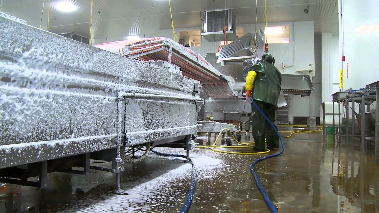
What requirements are put onto components exposed to washdown?

  • Stainless Steel resists corrosion and is polished to level the microscopic roughness that provides harborage for bacteria.
  • Special Component Ratings:
    • ECOLAB chemical testing for housings
    • FDA approved materials
    • 3A USA hygienic for US Equipment
    • EHEDG hygienic for European Equipment
  • IP69K is tested to be protected from high pressure steam cleaning per DIN40050 part 9; this is not guaranteed to be immersion rated (IP67) unless specifically identified.

If you are interested in what sensors, networking & RFID products are available for use in food and beverage manufacturing with a washdown environment, please visit www.balluff.us.

IP Ratings and ECOLAB Basics

Guest contributor:  Jack Moermond, Balluffwashdownsensors

Integrating sensors in washdown applications can be confusing when considering the

various approvals.  So what do they all mean?  If a sensor is an IP69K rated sensor does that mean it will survive everything?  In the world of sensors there is IP54, IP67, IP68 and IP69 so if my sensor is IP69K that means it is the best right?  The short answer is no.  Let’s take a brief look at the differences.

IP ratings will generally have two digits with the first digit referring to the solid particle protection.  The second digit indicates the level of protection against the ingress of water.

Sensors rated for IP54 indicates they are dust protected, meaning that dust can get inside the sensor, however, it cannot be enough to interfere with the operation of the equipment –  this is designated by the 5.  The 4 indicates that the sensor withstands splashing water on the housing from any direction with no detrimental effect.  The test for the splashing of water lasts at least five minutes with a water volume of 2.64 gallons per minute with a pressure of 7.25 to 21.76 PSI.

IP67 rated sensors are the most commonly used sensors on the market.  Even most electrical enclosures used in automation are IP67 rated.  The 6 indicates these devices will not allow the entry of dust.  The 7 indicates that the sensor can be immersed in water to a depth of 1 meter for 30 minutes.

IP68 rated sensors are dust tight sensors that can be immersed in water continuously under conditions specified by the manufacturer.  Typically the depth of the immersion is 3 meters.

The IP69K rating is based on a dust tight sensor that can withstand high pressure sprays.  The devices are sprayed with a pressure of 1,160 to 1,450 PSI.  The water temperature can be as high as 176°F with a flow rate of 3.7 to 4.2 gallons per minute.  The distance from the nozzle to the device is 4 to 6 inches.  The sensor is placed on a rotary table that rotates at 5 revolutions per minute and the sensor is sprayed for 30 seconds at four angles 0°, 30°, 60°, and 90°.

The ultimate sensor would have a rating of IP67/IP68/IP69 indicating that it will survive submersion and high pressure washdown.  Also, some of these sensors are 316L stainless meaning they have low carbon content and are more corrosion resistant than other stainless steel grades.  Are all IP69K sensors stainless steel?  No, some sensors utilize polycarbonate-ABS thermoplastic.

Usually during washdown applications in the food and beverage industry the spray is not just water but some sort of cleaning chemical or disinfectant.  These aggressive cleaning and disinfecting agents can attack different housing materials.  This is addressed by the ECOLAB certification.

The ECOLAB test consists of testing the housing and sensor materials to exposure to these aggressive cleaning and disinfecting agents.  The devices are tested for 14 to 28 days at a room temperature of 68° F.  During this time the sensor is visually inspected for swelling, embrittlement, or changes in color.

Don’t forget that even though the sensor has the correct IP rating for your application that the mating connector has to meet the same specifications.  For example, if the sensor is IP69K rated and a IP67 mating cable is used then the lower IP rating has precedence.

If you are interested in what sensors and cables meet washdown requirements, please visit www.balluff.us.

Basic operating principle of an Inductive Proximity Sensor

Guest contributor: Henry Menke, Balluff

Did you ever wonder how an Inductive Proximity Sensor is able to detect the presence of a metallic target?  While the underlying electrical engineering is sophisticated, the basic principle of operation is not too hard to understand.

At the heart of an Inductive Proximity Sensor (“prox” “sensor” or “prox sensor” for short) is an electronic oscillator consisting of an inductive coil made of numerous turns of very fine copper wire, a capacitor for storing electrical charge, and an energy source to provide electrical excitation. The size of the inductive coil and the capacitor are matched to produce a self-sustaining sine wave oscillation at a fixed frequency.  The coil and the capacitor act like two electrical springs with a weight hung between them, constantly pushing electrons back and forth between each other.  Electrical energy is fed into the circuit to initiate and sustain the oscillation.  Without sustaining energy, the oscillation would collapse due to the small power losses from the electrical resistance of the thin copper wire in the coil and other parasitic losses.

 Inductive proximity sensor cutaway with annotation

The oscillation produces an electromagnetic field in front of the sensor, because the coil is located right behind the “face” of the sensor.  The technical name of the sensor face is “active surface”.

When a piece of conductive metal enters the zone defined by the boundaries of the electromagnetic field, some of the energy of oscillation is transferred into the metal of the target. This transferred energy appears as tiny circulating electrical currents called eddy currents.  This is why inductive proxes are sometimes called eddy current sensors.

The flowing eddy currents encounter electrical resistance as they try to circulate. This creates a small amount of power loss in the form of heat (just like a little electric heater). The power loss is not entirely replaced by the sensor’s internal energy source, so the amplitude (the level or intensity) of the sensor’s oscillation decreases.  Eventually, the oscillation diminishes to the point that another internal circuit called a Schmitt Trigger detects that the level has fallen below a pre-determined threshold.  This threshold is the level where the presence of a metal target is definitely confirmed.  Upon detection of the target by the Schmitt Trigger, the sensor’s output is switched on.

The short animation to the right shows the effect of a metal target on the sensor’s oscillating magnetic field.  When you see the cable coming out of the sensor turn red, it means that metal was detected and the sensor has been switched on.  When the target goes away, you can see that the oscillation returns to its maximum level and the sensor’s output is switched back off.

Want to learn more about the basic operating principles of Inductive Proximity Sensors? Here’s a short YouTube video covering the basics: