Why Rexroth? Top Four Reasons to Choose Rexroth Drives & Controls

Todd Sharp, Motion Control Sales Manager, CMA/Flodyne/Hydradyne

CMA/Flodyne/Hydradyne is a leader in the design and commission of drive and control
systems for our customers for over 30 years, and one question that we often hear is “Why is Rexroth the best?”  There are many brands competing for the drive and control market, and here at CMAFH, we have working experience with most if not all of them. Our engineers program,  repair and upgrade many of the brands of control systems, and we have the ability to integrate any brand into our custom projects at our customer’s request. Having specialized in Bosch Rexroth products for many years, we understand the unique strengths of the product line.

Rexroth drives and controls can be differentiated from competing brands in four very distinct ways.

1. Product Breadth

The IndraDrive product family spans the power range from 100W to 4MW. This product family can operate as an open loop frequency drive/sensor less vector drive up to a multi-axis integrated motion and logic controller that can be either stand alone or drive resident. The IndraDrive product family also includes a cabinet free drive integrated motor. This entire IndraDrive product family is supported by the same software.Indradrive 2016 13187

  • Power range from 100W to 4MW
  • Range of technology from open loop V/F and sensor-less vector control to multi-axis integrated motion and logic control
  •  Integrated motion and logic control – controller or drive resident
  •  Cabinet free drive integrated motor

2. Connectivity

Rexroth’s drive and control platform supports all common communication buses including Ethernet I/P, EtherCAT, Profinet, SERCOS, CANopen, Powerlink, Profibus.
We can control 3rd party motors regardless of brand or type, and we can operate all common feedback types including TTL, 1vpp, Endat, Hiperface, SSI, resolver. Our drives are available with a 2nd encoder input with a 1MHZ input frequency. Our control supports all common machine programming languages like ladder, FB, ST, IL… plus all common IT and engineering languages like C#, C++, Java, Labview, Matlab.

  • Supports all common communication buses including, Ethernet I/P, EtherCAT, ProfiNet, SERCOS, CANopen, Keyvisual_inkl_Logos_w486Powerlink, Profibus
  • Controls all 3rd party motors regardless of brand or technology type
  • Operates all common feedback types (TTL, 1vpp, ENDAT, Hiperface, SSI, resolver) with drive based second encoder input with up to 1MHZ input frequency
  • Supports all common machine programming languages (ladder, FB, structured text, instruction list) plus all common IT and engineering type languages like C#, C++, Java, Labview, Matlab

3. Functionality

Whether it’s drive or controller based, Rexroth offers multi-zone tension control, vibration dampening/anti-slosh control, high speed registration control, advanced electronic camming and hydraulic control. We also support zoned safety control with safe torque off and full safe motion; controller or drive based. Yes, drive based safe motion control!

  • PMK2801_02R_WEBMulti -zone tension control
  • Vibration dampening/anti-slosh control
  • High speed registration control
  • Advanced electronic camming
  • Supports all common hydraulic functions
  • Integrated safe torque off and safe motion control


4. Support

Rexroth designs, engineers and manufactures all products they sell. All are standard and sold throughout the world. In the US, hundreds of local high-tech distributors are Rexroth trained and certified to provide full sales, service and application support.  Additionally, Rexroth maintains sales, service and application support facilities in every region of the US, plus scores more globally.

  •  All products are standard and sold throughout the world
  • Bosch Rexroth maintains sales, service and application support facilities in every region of the US and scores more globally
  • In the US hundreds of local high-tech distributors are Rexroth trained and certified to provide additional sales, service and application support

Bosch Rexroth_2012

Do you have questions about this post?  Please contact us:

← Back

Thank you for your response. ✨

Warning
Warning
Warning
Warning

Warning.

About CMA/Flodyne/Hydradyne

cropped-cmafh-logo-with-tagline-caps.png

CMA/Flodyne/Hydradyne is an authorized  Bosch Rexroth distributor in Illinois, Wisconsin, Iowa and Northern Indiana.

In addition to distribution, we design and fabricate complete engineered systems, including hydraulic power units, electrical control panels, pneumatic panels & aluminum framing. Our advanced components and system solutions are found in a wide variety of industrial applications such as wind energy, solar energy, process control and more.

Resources:

Engineered Systems Capabilities

Shop for drives online

Indramat Repair Center

Rexroth Drives & Controls Training

Press productivity improves with controller upgrade

Guest contributor: Richard Meyerhoefer, Delta Computer Systems

Fastener stamping machine output triples after tuning the motion with a solution from Delta Computer Systems.

Improving the productivity of a manufacturing process by speeding up the operation of an old machine can be very difficult, driving plant managers to purchase new equipment. It’s often possible, however, to replace the control system, maintaining the old mechanics, and get the performance of a new machine for much lower cost. Hydraulics distributor CMA/Flodyne/Hydradyne (CMAFH) of Hanover Park, Illinois, recently assisted in such an upgrade for a manufacturer of fastening components. The machine was a press used to imprint patterns on the surface of metal fasteners with a punch that fits into the bottom of a 4″ bore hydraulic cylinder (Figure 1). As the punch comes down it reshapes the top of the fastener and its edges to provide a locking feature.

Motion controller selection

Figure 1. Diagram showing motion controller connections in the fastener press machine

In the past, the manufacturer used a programmable logic controller (PLC) to operate a two-position, bang-bang valve to drive the cylinder, but company engineers found imprecise results that limited production to around 60-to-70 parts per minute. As a result, the company moved to a proportional valve and closed-loop controller that operated the valve based on cylinder position/acceleration. The controller would open the valve quickly and then back off the valve as the cylinder got closer to making contact with the fastener. This method enabled an increase in production to approximately 140 parts per minute. But to meet competitive pressures, company managers demanded the rate be increased, driving the need for a new electro-hydraulic motion controller.

Company engineers called CMAFH, with whom they had worked on automation solutions for more than 20 years, to recommend a new controller for the company’s old bang-bang machine.

Hooking up the controller

The Delta RMC75E motion controller (Figure 2), recommended by CMAFH engineering manager Norman Dziedzic, accurately controls position and force, to control acceleration with more precision than the closed-loop controller previously used. Dziedzic programmed the motion controller to move the cylinder to a predetermined position while monitoring the force being applied by the punch. When the force reaches a particular value, the controller is switched to force control mode to ensure that adequate force is ultimately applied to the fastener. The old closed-loop control system used position control only, with some input from a load cell within the tool to verify that a certain minimum force was applied to the part.

“The Delta controller operates similar to that, but is easier to control,” says Richard Mellor, engineer at the fastener company. Every motion step made by the other controller was initiated by the PLC, and there was lag time in passing position information. “The beauty of the Delta controller is that the motion program now resides in the controller,” Mellor adds.

Now, the PLC just does overall machine control, triggering the Delta RMC to press the part at the appropriate time. When the pressing operation is complete, the Delta controller knows, based on the position and force ranges inputted to the controller, whether the pressed part is a good part or a bad one, and notifies the PLC. The Delta RMC75E gets cylinder position feedback from a linear magnetostrictive displacement transducer (LMDT) via a synchronous serial interface (SSI) to the controller. To measure force, the system uses a fatigue-rated (rugged) force transducer (shown in Figure 1).

Programming, tuning

Figure 2.  The Delta RMC75E motion controller can control up to two motion axes simultaneously

Dziedzic set up the motion program initially, and he fine-tuned the loop parameters working with a fastener company engineer. The two also developed the code to implement quality testing of the finished parts.

“I find the Delta very easy to program, but I have 30 years in as a controls engineer. If you’ve had anything to do with PLC or message display packages, it’s relatively intuitive to find your way around,” Mellor says

For tuning the motion, Dziedzic relied heavily on Delta Computer Systems’ Plot Manager software, which allows an engineer to view multiple key motion parameters versus time on a single graph (Figure 3). The plot shows three press cycles, where the red curve is the actual position of the press cylinder, the blue curve is the actual velocity of the cylinder, and the force being applied by the die to the work piece is shown by the black line. The cyan line is the target cylinder position. When the motion system is perfectly tuned, the actual cylinder position curve overlaps the target position, indicating that any positioning error caused by the mechanical aspects of the system – for example, the compressibility of the fluid or the friction of the moving parts – has been compensated for by the control algorithm. In Figure 3, the flat yellow line indicates the command force which must be applied to the part to make the press operation successful. The circle marked A highlights the point in time when the actual position (red line) begins to deviate from the target position (cyan line) as the tool comes into contact with the part. This is also when the force (black line) begins to climb. Then, at point B, the change in actual velocity (blue curve) shows force control taking over from position control. Area C in the plot shows when the actual force meets the target command force to signal a successful operation. Area D shows harmless motion transients that are caused by retracting the cylinder quickly to prepare for pressing the next part.

Using the Plot Manager, motion characteristics that occur too quickly to be visible to the naked eye can be analyzed and corrected if necessary, enabling the manufacturing process to be accelerated.

Results

Figure 3.  Delta’s RMCTools plot Manager software shows axis position and force versus time, enabling precise tuning of the motion.

One of the fastener company’s other key requirements on the controller upgrade project was to provide a means of accessing process data using the controller in order to do a pass/fail test on the finished parts.

“We track final position reached and maximum force achieved,” Dziedzic says. Previously, the company needed an external analog device to do this. Now, the Delta RMC75E eliminates this need by making process parameters available for the PLC to read directly over Ethernet. “The fact that the Delta controller can do this in addition to controlling the cylinder provides a huge benefit to them.”

“We have been very happy with the performance increase we have gotten with the Delta motion controller,” Mellor adds. “Even if we hadn’t gotten the performance, Delta’s ease of use in system setup and tuning would have made the difference.”

With the Delta RMC75E controlling the operation of the cylinder, the machine can now process up to 180 fasteners per minute.

“We can move faster because we have more control over the proportional valve, yielding tighter control loops and better control of the gain in the system,” Mellor says.

Another advantage of using the Delta RMC is operation repeatability; the controller is able to control the force exerted in each cycle to a tolerance of ±40 lb out of 10,000 lb applied.

ABOUT US

cropped-cmafh-logo-with-tagline-caps.png

CMA/Flodyne/Hydradyne is an authorized  Delta Computer Systems distributor in Illinois, Wisconsin, Iowa and Northern Indiana.

In addition to distribution, we design and fabricate complete engineered systems, including hydraulic power units, electrical control panels, pneumatic panels & aluminum framing. Our advanced components and system solutions are found in a wide variety of industrial applications such as wind energy, solar energy, process control and more.

Enhancing Stepper Motor Systems with Linear Encoders

Guest contributor, Henry Menke, Balluff

Tabletop automation is a trend that is gaining momentum, especially in the fields of medical laboratory automation and 3D printing. Both of these applications demand a level of linear positioning accuracy and speed that might suggest a servomotor as a solution, but market-driven cost constraints put most servos out of financial consideration. New advances in stepper motor design, including higher torque, higher power ratings, and the availability of closed-loop operation via integrated motor encoder feedback are enabling steppers to expand their application envelope to include many tasks that formerly demanded a servo system.

Meeting the Demand for Even More Accurate, More Reliable Positioning

As tabletop automation development progresses, performance demands are increasing to the point that steppers systems may struggle to meet requirements. Fortunately, the addition of an external linear encoder for direct position feedback can enhance a stepper system to enable the expected level of reliable accuracy. An external linear encoder puts drive-mechanism non-linearity inside the control loop, meaning any deviations caused by drive component inaccuracy are automatically corrected and compensated by the overall closed-loop positioning system. In addition, the external linear encoder provides another level of assurance that the driven element has actually moved to the position indicated by the number of stepper pulses and/or the movement reported by the motor encoder. This prevents position errors due to stepper motor stalling, lost counts on the motor encoder, someone manually moving the mechanism against motor torque, or drive mechanism malfunction, i.e. broken drive belt or sheared/skipped gearing.

Incremental, Absolute, or Hybrid Encoder Signals

bmlThe position signals from the external encoder are typically incremental, meaning a digital quadrature square wave train of pulses that are counted by the controller. To find a position, the system must be “homed” to a reference position and then moved the required number of counts to reach the command position. The next move requires starting with the position at the last move and computing the differential move to the next command position. Absolute position signals, typically SSI (synchronous serial interface) provide a unique data value for each position. This position is available upon power-up…no homing movement is required and there is no need for a pulse counter. A recent innovation is the hybrid encoder, where the encoder reads absolute position from the scale, but outputs a quadrature incremental pulse train in response to position moves. The hybrid encoder (sometimes referred to as “absolute quadrature”) can be programmed to deliver a continuous burst of pulses corresponding to absolute position at power up, upon request from the controller, or both.

For more information about magnetic linear encoder systems, visit www.balluff.us.

CMAFH resources for Balluff Linear Encoders

Secure Protection from Attacks, Malicious Software and Unauthorized Access

Guest contributors: Gerrit Boysen and Mariam Coladonato, Phoenix Contact

High system availability is very important in process engineering, because ongoing processes must not be interrupted. A fence is a physical, easily identifiable safety measure to secure systems from unauthorized persons. In addition to such physical protections, implementing IT security practices is also becoming more important.

The current trend toward interconnectivity is driving the growing need for IT security in process engineering. Not only is there an increasing number of horizontal interconnections from one system to another, but also the field level is more connected to the office level. In addition, all levels are using more and more Ethernet components. The good news is that this interconnection increases efficiency and reduces costs. The downside of this, however, is that it also increases the risk that malicious software will quickly spread throughout all areas of a company.

In light of this information, process-engineering systems are repeatedly being threatened by new security gaps and a growing number of malicious programs. The computers and control systems used in industrial networks must have much more extensive protection from attacks, malicious software, and unauthorized access than they have so far (Figure 1).

Figure_1phoenixcon

Figure 1: The Process Analysis Center is protected by a firewall.

The security strategies used in conventional office IT, however, usually are not designed for industrial systems. Industrial networks require special protective measures. The IT systems used in production environments differ fundamentally from those used in office environments in four ways.

  1. Patches cannot typically be applied to industrial systems
  2. Industrial systems use special protocols such as OPC Classic, which are not used in the office world
  3. Large systems can have structurally identical modular assemblies with identical IP addresses
  4. Production systems often require different firewall rules and standards during maintenance and in the event of remote servicing

Office PCs usually have virus scanners that perform security updates at regular intervals. These measures do not normally work for industrial systems for a few reasons. Sometimes, the manufacturer of the operating systems or applications used in the industrial sector no longer provides security updates. In addition, test measures must be performed on industrial PCs before each operating system, antivirus software, or application update, and this cannot be done efficiently in terms of operation.

The use of specific industrial firewalls can protect these non-patchable systems against attacks from outside the network. To do this, hardware-based firewall appliances are connected between industrial PCs and outside networks. Another advantage of using external security hardware is that the system’s resources do not have to be used for security tasks (Figure 2).

Figure_2phoenixcon.jpg

Figure 2: Security example from the process industry.

Targeted restriction of network communications

With firewalls, the user can configure the protocols and ports that can be used to access the protected systems. This can prevent or at least limit the attempt of an attacker to gain access to the network through insecure ports. The Stateful Packet Inspection Firewall approach is an ideal way to manage these systems. This approach uses rules to filter incoming and outgoing data packets in both directions: from the outside to the protected internal network and vice versa. Based on the protocol, source addresses and ports and destination addresses and ports can be used to limit network communications selectively to a defined scope required for production. Here, the Connection Tracking function identifies the response packets on permitted connections and lets them through.

When selecting a suitable firewall, the engineer must ensure that the selected firewall understands any protocols used in the particular industry. Otherwise, reliable protection cannot be guaranteed. For example, office firewalls typically do not support industrial protocols such as OPC Classic, so they cannot provide appropriate protection for the application.

While conventional firewalls cannot reliably protect data traffic via OPC Classic, industrial variants – such as one with a license for OPC Inspector – can provide a suitable solution. The firewall checks the OPC Classic communications data packets and filters them precisely, based on Deep Packet Inspection. For this purpose, the Stateful Inspection principle is also applied to OPC Classic data. This means that the firewall identifies the port changes negotiated in the OPC Classic protocol and approves them dynamically. In this context, it inspects whether a port opened by OPC is used within a timeout period and whether the data traffic moving through this port corresponds to the OPC protocol. This method provides high-access security (Figure 3).

a_0065449

Figure 3: Deep Package Inspection in the OPC protocol.

Unique and clear mapping to virtual external networks

Complex production sequences are typically structured into networked, largely standalone cells. For an efficient design of the engineering, documentation, and cell operation, the use of identical IP addresses for all systems of a single type proves to be advantageous. If all communications are initiated from the internal cell networks, several identical systems can be connected with simple masquerading NAT (Network Address Translation) routers to the operator’s production network. If the higher level network also needs to establish a connection to the individual cell nodes, however, this solution is not sufficient, because the cell nodes cannot be addressed from the outside. In this case, the user requires a router that can map internal machine networks universally or selectively to unique virtual external networks using 1:1 NAT.

Because of this, an industrial firewall offers the so-called 1:1 NAT routing function, in addition to the pure NAT routing. OPC Inspector, mentioned above, allows this NAT function for the OPC Classic protocol. This sets it apart from conventional office firewalls and other industrial firewalls.

Event-controlled (de)activation of firewall rules

Different firewall rules and standards have advantages in different situations. This is because during production operation or maintenance and remote system servicing, different connections are allowed or forbidden. In practice, the user usually solves the problem by summarizing the various firewall requirements in a set of rules. This procedure inevitably lowers the level of security, because the firewall rules allow all connections required for the different operating states, even if they are not required for the current operation.

An industrial firewall solves the problem by implementing a Conditional Firewall. This function allows the firewall rules to be activated or deactivated depending on events. A variety of events – such as an externally connected button, switch, control window in a web interface, API command line, or establishing or disconnecting a VPN (Virtual Private Network) connection – can be selected to trigger a specific firewall rule (Figure 4).

Rexroth-BR_Catalog2 (1)

Figure 4: Secure remote access to the system.

Summary

The requirements placed on a firewall in a production zone are different from those in the office world. Therefore, using an industrial firewall with a NAT function can support the individual, simple segmentation of networks. This allows the Defense-in-Depth concept based on the ISA-99 and IEC 62443 international standards to be implemented even in systems using the OPC Classic protocol.

Twelve tips for better cylinder selection

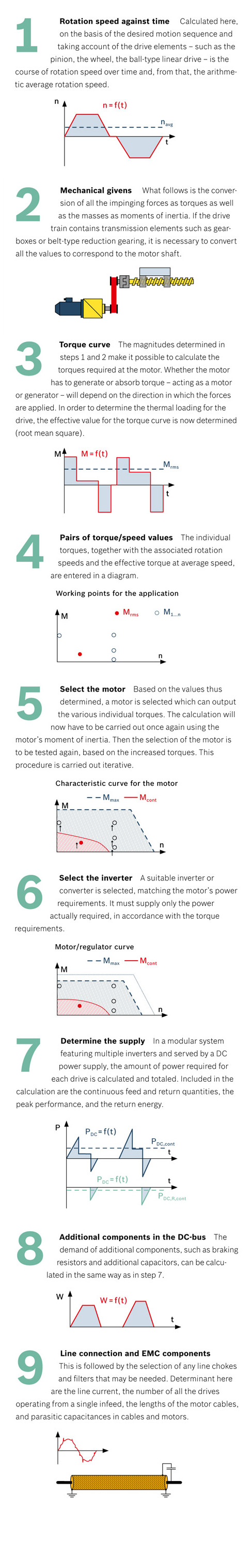
Guest contributor: Marty Hegyi Product Manager, Cylinders, Bosch Rexroth Corp.

Here’s how to design hydraulic cylinders that improve performance, last longer and cost less.

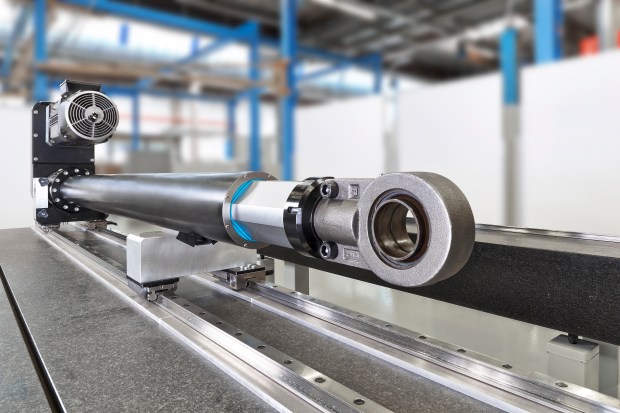
Hydraulic cylinders harness fluid pressure and flow to generate linear motion and force, and they work well in both industrial machines, like presses and plastic-molding machines, and in mobile equipment, like excavators and mining trucks. And when compared with pneumatic, mechanical or electric linear-motion systems, hydraulics can be simpler, more durable and offer significantly greater power density.

Rexroth-photo-1_large-hydraulic-cylinders

Bosch Rexroth builds large hydraulic cylinders with bores to 1.5m and strokes to 24 m

Hydraulic cylinders are available in an impressive array of types and sizes to meet a wide range of application needs. Choosing the right cylinder is critical for maximum performance and reliability. Here are 12 practical tips for selecting, sizing and operating the best one for a job.

Selection considerations

1. Choose the right cylinder type. Two basic hydraulic cylinder designs for industrial applications are tie-rod and welded cylinders.

Tie-rod cylinders use high-strength threaded steel tie rods on the outside of the cylinder housing for additional strength and stability. In the U.S., this is the most common cylinder type. They’re used on most general industrial applications, such as plastics machinery and machine tools, although they tend to be limited to 3,000 psi maximum operating pressure. The cylinders are built to NFPA standards, which makes their dimensions and pressure ratings interchangeable with any other cylinder built to that standard.

Welded or mill-type cylinders have a heavy-duty housing with a barrel welded or bolted directly to the end caps and require no tie rods. Designed for higher pressures, to 5,000 psi

Rexroth-photo-3_mill-type-cylinder

Mill-type cylinders have a heavy-duty housing with a barrel welded or bolted directly to the end caps

Mill -type cylinders have a heavy-duty housing with a barrel welded or bolted directly to the end caps and require no tie-rods

or greater, they are generally preferred in more-rugged applications such as presses, steel mills and offshore settings with harsh environments and wide temperature swings.

Unlike U.S. OEMs, European manufacturers typically use mill-type cylinders in almost all general industrial applications. (They also use tie-rod cylinders, but generally for lower-pressure tasks up to 160 bar (2,350 psi).) However, due to the design, tie-rod cylinders are less expensive than mill-type cylinders—another reason for widespread use in the U.S.

Also keep in mind that cylinders are often customized. NFPA cylinder standards dictate dimensions, pressure ratings, type of mountings, and so on—they’re standard catalog products. However, engineers designing custom machinery often need to deviate from the standards with special mountings, port sizes or configurations to suit a particular application. About 60% of the cylinders sold in the U.S. are catalog items, while 40% are modified products with unique requirements.

2. Select the proper mountings. Mounting methods also play an important role in cylinder performance. The cylinder mounting method first depends on whether the cylinder body is stationary or pivots.

For stationary cylinders, fixed mounts on the centerline of the cylinder are usually best for straight-line force transfer and minimal wear. Among the different variations, flange mounts are generally preferred. Loads are centered on the cylinder and opposing forces are equally balanced on rectangular or round flanges. They’re strong and rigid, but have little tolerance for misalignment. Experts recommend cap-end mounts for thrust loads and rod-end mounts for pull loads.

Centerline lug mounts also absorb force on the centerline, but require dowel pins to secure the lugs to prevent movement at higher pressures or under shock conditions.

Side-mounted or foot-mounted cylinders are relatively easy to install and service, but

Rexroth-BR_Tie-Rod-Cylinders

Tie-rod cylinders have high-strength threaded steel tie rods on the outside of the cylinder  housing for added strength and stability

they generate offset loads. The mounts experience a bending moment as the cylinder applies force to a load, potentially increasing wear and tear. Heavy loading tends to make long-stroke, small-bore cylinders unstable.

Side and foot mounts need to be well aligned and on the same plane, and the load supported and guided. Otherwise, induced side loads due to misalignment lead to cylinder wear and seal leaks. Engineers also must be concerned with shear forces on the bolts. Add a dowel or shear pin and keyway behind the feet to prevent the forces from potentially shearing the mounting bolts. If necessary for extra support, add another set of foot mounts in the cylinder midsection in addition to those on the head and cap ends.

3. Select the right pivot mountings when the cylinder body moves. Pivot mounts absorb force on the cylinder centerline and let a cylinder change alignment in one plane. Common types include clevis, trunnion and spherical-bearing mounts.

Clevis mounts can be used in any orientation and are generally recommended for short strokes and small to medium-bore cylinders. Cylinder engineers prefer clevis mounts with spherical bearings over those with plain bearings because they allow for a bit more misalignment and are, thus, a bit more forgiving. However, if using a spherical bearing on a rear clevis, they also recommend a rod-end attachment that pivots—such as a spherical rod eye. The combination helps compensate for any side loading or potential misalignment.

Trunnion mounts come in head, mid and rear-mount versions. The mid-trunnion design is likely most common, as it offers designers a bit more flexibility. They can be specified exactly in the cylinder mid-section or most anywhere toward the front or rear as the application demands. Once specified, however, the mount is not adjustable.

Sizing considerations

For all types of cylinders, important parameters include stroke, bore diameter, rod diameter and pressure rating.

4. Piston-rod diameter is critical. Perhaps the most common error in hydraulic design is underspecifying the piston rod, making a cylinder more prone to stress, wear and failure. Piston-rod diameters can range from 0.5 to more than 20 in., but they must be sized for the available loads. In a push application, it is extremely important to size the rod diameter properly, based on Euler calculations, to avoid rod buckling or bending.

When designing a cylinder to generate a required force, sizing the rod is always the first consideration. From there, work backward and determine bore size for the available pressure, and so on.

5. Prevent rod bending. In cylinders with long strokes, a fully extended rod can bend under its own weight. Excessive bending leads to wear and damage to seals and bearings. It could even cock the piston inside the bore, which can score and damage the inner surface of the cylinder. Rod deflection should never exceed 1 to 2 mm.

Cylinder rods that are at risk for bending or misalignment require additional support. Depending on the stroke length, a stop tube—which increases the bearing area of the cylinder—may be required to prevent excessive wear and jack-knifing. Engineers might also consider a larger diameter rod, which increases strength. But that also increases weight and may be self-defeating, so do the math carefully. In extreme cases, users may also need to add external mechanical support for the rod, such as a saddle-type bearing.

6. Watch out for impact loads. Stroke length, the distance needed to push or pull a load, can vary from less than an inch to several feet or more. But when the cylinder extends or retracts, ensure that the piston doesn’t bottom out and generate impact loads at the end of stroke. Engineers have several options: Add internal cushions to decelerate the load near the end of stroke; add an external mechanical stop that prevents the cylinder from bottoming out; or use proportional-valve technology to precisely meter flow and safely decelerate the load.

7. Weigh bore diameter versus operating pressure. To produce a given amount of force, engineers can specify large-bore cylinders that operate at low pressures, or vice versa. Generally, systems that operate at higher pressures but with smaller cylinders are more cost effective. Also the benefits cascade. Smaller cylinders require less flow and, in turn, smaller pumps, lines, valves and so on. Many installations see an overall cost reduction by moving to higher pressures.

That said, cylinders are rated for both nominal (standard) pressure and test pressure to account for variations. Systems should never exceed the nominal rated design pressure of a cylinder.

8. Add a factor of safety. While design calculations are essential, real-world operations differ from theoretical results. Always assume peak loads will require additional force. The rule of thumb is to choose a cylinder with a tonnage rating of 20% more than required for the load. That compensates for losses like friction from the load, efficiency losses in the hydraulics, actual pressure below the rated system pressure, slip-stick on cylinder seals and bearings, and so on.

Operating considerations

Cylinder parameters like stroke and force must match machine requirements, but that is only half the challenge. Environmental and operating demands also play a major part in determining a cylinder’s ultimate success.

9. Match the seals to the job.Seals are probably the most vulnerable aspect of a hydraulic system. Proper seals can reduce friction and wear and increase service life, while the wrong seal leads to downtime and maintenance headaches. It probably goes without saying, but ensure the seal material is compatible with the fluid. Most hydraulics use a form of mineral oil, and standard Buna-N seals tend to work well. But applications involving synthetic fluids, such as phosphate esters, require Viton seals. Polyurethane is also incompatible with high water-based fluid such as water glycol.

Regardless of the fluid, keep it clean. Contamination and dirt in the fluid will damage Rexroth-BR_CylinderApplicationseals. It can also score the inside of the barrel and eventually ruin the cylinder.

If operating temperatures exceed 300° F, standard Buna-N nitrile rubber seals may fail. Viton synthetic rubber seals generally handle temperatures to 400° F and fluorocarbon seals even higher. When in doubt, assume conditions will be worse than they first appear.

10. Add a gland drain. Probably 90% of cylinder failures are due to the seals. That holds even if engineers specify the proper seals for the fluid, pressure, environment and application as they wear out over time and need replacement. Most experts recommend that seals should be maintained periodically, rather than waiting for failure at a usually inopportune time.

If cylinders are in hard-to-access locations that makes maintenance difficult, or if leaks will damage products or lead to costly downtime, order cylinders with a “gland drain.” This is a special port machined into the cylinder head between primary and secondary seals; or between primary and rod wiper. Then, if the primary rod seal begins to fail and leak, oil bypasses the seal and flows out the gland-drain port—generally through tubing to a collection bottle. If oil collects in the normally empty bottle, it gives a visual indication that seals are wearing out and will soon need replacement.

Cylinders usually have a secondary rod seal or a double-lip rod wiper that temporarily prevents oil from leaking out the rod end, giving maintenance personnel time to schedule repairs.

11. Watch the materials. The type of metal used for the cylinder head, base and bearing can make a significant difference. Most cylinders use SAE 660 bronze for rod bearings and medium-grade carbon steel for heads and bases, which is adequate for many applications. But stronger material, such as 65-45-12 ductile iron for rod bearings, can provide a sizable performance advantage for tough industrial tasks.

Also consider extreme temperatures. Typical carbon steels used in cylinder components are generally suited for around –5 to 200° F. In arctic conditions well below 0° F, for example, standard steel can become brittle and may require alternative materials.

12. Protect the rod. Because the piston rod meets the outside environment, it must resist attack from water, salt air, corrosives, and other harmful substances. In general industrial applications, carbon steel with chrome plating is the norm. But in wet or high humidity environments, such as marine hydraulics, 17-4PH stainless steel with chrome plating is used for most piston rods. Some cylinder manufacturers offer special protective coatings. Bosch Rexroth, for example, offers Enduroq, which is a proprietary thermal-spray coating or plasma-welded overlay that’s applied to rods for extreme corrosion protection and high wear resistance. It’s used in harsh environments, typically for specialty large-bore, long-stroke cylinders.

For dirty, abrasive conditions, engineers have a love/hate relationship with protective rod boots. Installing a boot over the rod keeps out dirt, metal shavings and other external contamination that would otherwise damage the rod and eventually the seals. However, if the boot punctures or rips, dirt gets drawn in and may not get out, which is worse than no boot at all. Maintenance personnel must routinely check for worn or torn boots that could accelerate damage to the cylinder.

Don’t overlook sizing software

Sizing software for cylinders is a great tool, but more engineers need to take advantage of the benefits it offers. These programs address most, if not all, of the pertinent questions designers need to answer to spec the right cylinder.

One such program developed by Bosch Rexroth is the Interactive Catalog System Rexroth-BR_Catalog2 (1)(www.boschrexroth.com/ics). It lets users enter parameters like force, pressure, load, angle of installation and mounting type, and the software sizes the cylinder, lists variations that meet the criteria and offers possible alternatives. It also lets engineers select and test cylinders on-screen before specifying the actual components. In addition, ICS generates dimensional drawings and 2D or 3D models for direct import into AutoCAD or other CAD software.

CMAFH Resources

Shop online for Rexroth hydraulic products here

Considerations for Industrial Enclosure Cooling

Guest contributor, Eric Corzine, Product Manager – Climate Control, Rittal

Data Centers and server racks run hot. Protecting the technology backbone of your company means managing air flow, temperature, energy consumption and cooling technology.

Rittal, the world’s largest enclosure manufacturer and a leader in thermal management of electrical, electronic and IT equipment, offers some important guidelines to ensure your equipment stays in optimum condition. The following tips are based on decades of practical experience in the use of enclosures climate control solution in industrial environments. By ensuring sufficient planning and maintenance guidelines are in place, control cabinets and electronic enclosures can be last longer and be more energy-efficient.

7 Considerations for More Efficient Enclosures

1. Devices and electrical components must be installed in the enclosure in accordance with the manufacturer instructions. Storage space for necessary documents and circuit diagrams should also be taken into account during the planning phase.

2. When arranging the components in the enclosure, verify that the cooling air flows from top to bottom. You can ensure this in the planning stages by properly routing the air flow away from the electronic components. When roof-mounted units are used, particular attention needs to be paid to the air flow from blowers built into electrical components. The use of air duct systems is advisable in the case of roof-mounted cooling units

Proper Enclosure Heat Dissipation

3. There should be sufficient space for air to flow between the parts and electrical components.

4. Air intake openings of climate control components must not be obstructed by electrical devices equipment or cable ducts. With all climate control solutions, the cold air should always be routed close to drive units. This is where the greatest heat losses occur. This arrangement ensures that the cold supply air from the climate control solution optimally cools the drive units without losses.

Air intake design for cooling enclosures

5. Internal temperatures of the enclosure should always be set to +35◦C. There is no technical justification for setting the temperature any lower. If the temperature inside the enclosure is any lower, condensation will be significantly increased.

6. Institute a systematic cleaning cycle. As most climate control components are used in industrial environments external filters of the climate control must be maintained to ensure long-lasting operation.

7. Ensure the correct filters are used for the industry application.

PU Filter for Industrial Enclosure Cooling

In heavily dust-laden atmospheres, PU filters should be used and replaced on a regular basis. Cooling units with Ri Nano coating typically do not need a dust filter.

Metal Filter for Enclosures

If the air is oil-contaminated, use metal filters. These separate the oil condensate from the air and can be cleaned with appropriate detergents

Textile Enclosure Lint Filter

In the textile industry, the use of lint filters is recommended.

Fiber Mat Filter

Chopped fibre mat filters are not suitable for cooling units.

CMAFH Rittal Resources:

Rittal Wallmount Program

Rittal Enclosure and Process Cooling handbook

Rittal Innovations 2016

How do I see PLC data from my smartphone?

Guest contributor, Pat Millot, Balluff

From my smartphone, I can do anything from making coffee to adjusting my home thermostat. This wave of appliances and other physical devices connecting and communicating through a network is known as the Internet of Things and it’s playing a crucial role in industry. With the Industrial Internet of Things (IIoT) we can now monitor PLC data without ever intruding on the PLC. Let’s take a look at how I implemented PLC tags on a web application.

IIoT_computer The first step is to download OPC UA historian software. OPC UA stands for Open Platform Communications Unified Architecture. OPC is a client/server communication standard that was made as a gateway between the PLC and a Windows PC. The UA was added as an upgrade that allowed communication across other operating systems such as Linux and iOS along with other added functionality improvements. Once this software is running and the PLC and PC are communicating, we can work on hosting that data.

IIoT_StructureHosting the controller data can seem like a daunting task at first due to the many different options in software and programming languages to use. For example: Ruby, PHP, ASP, ASP.NET and much more are available for back-end development. For my web app, I used SQL to host the data from the OPC UA software. As for the back-end, I went with node.js because it has great packages for working with SQL; in addition to the fact that node.js uses JavaScript syntax which I’m familiar with. The front end of the app was written with HTML and CSS with JavaScript for interactivity. With all these elements in place, I was ready to host the server on the PC to host PLC data.

With smart IO-Link sensors on our conveyor I was able to look at diagnostic and functional data in the PLC and setup an interactive screen at the conveyor for viewing production and maintenance information.

And now I can even check my sensor outputs with the same smartphone that just made my coffee and adjusted my office’s temperature.

IIoT_warehouse

You can learn more about the Industrial Internet of Things at www.balluff.us.

Shop Balluff products online at www.cmafh.com

Which cable is best for your application?

Guest contributor, Janet Czubek, Balluff

There are many different types of cable jackets and each jacket works well in a specific application.  The three main sensor cable jackets are PVC (Polyvinyl Chloride), PUR (polyurethane) and TPE (thermoplastic elastomer). Each jacket type has different benefits like washdown, abrasion resistant or high flexing applications.  Finding the correct jacket type for your application can extend the life of the cable.PVC

PVC is a general purpose cable and is widely available.  It is a common cable, and typically has the best price point.  PVC has a high moisture resistance, which makes it a good choice for wash-down applications.

PUR
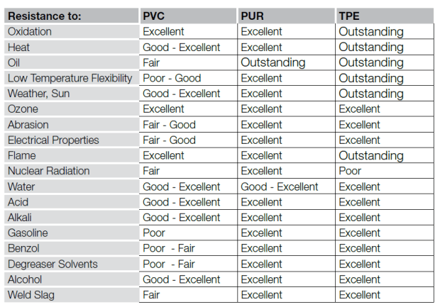
PUR is found mostly in Asia and Europe.  This cable jacket type has good resistance against abrasion, oil and ozone.  PUR is known for being Halogen free, not containing: chlorine, iodine, fluorine, bromine or astatine.  This jacket type does have limited temperature range compared to the other jacket types, -40…80⁰C.

TPETPE is flexible, recyclable and has excellent cold temperature characteristics, -50…125⁰C.  This cable is resistant against aging in the sunlight, UV and ozone.  TPE has a high-flex rating, typically 10 million.

The table below details the resistance to different conditions. Note that these relative ratings are based on average performance. Special selective compounding of the jacket can improve performance.

resistanceto2

Choosing the right jacket type can help reduce failures in the field, reducing downtime and costs.  Please visit www.balluff.us to see Balluff’s offering of sensor cables in PVC, PUR and TPE.

Nine steps to the proper drive

Guest contributor, Bosch Rexroth

A fully structured approach, well-founded knowledge of the formulae and a fundamental understanding of the technology are essential to designing drives. These are the prerequisites for perfect matching of the machine and the drive.18089-x734_w734

Drive engineering is undertaken when the machine is initially designed, and also when the requirements for the machine have changed or a retrofit is due. Leaving excess tolerances – either upward or downward – is counterproductive for the design. If the drive is under-dimensioned, then the machine will not achieve the desired performance level and, in the worst case, the drive will have to be changed out for a more powerful one. That involves major outlays. The procurement costs will rise and because of poor efficiency, the life-cycle costs will increase. But what does designing a drive mean? It means laying out the motor’s torque curve so that it ideally matches the needs of the machine being served.

Technical understanding is a prerequisite

Software can provide assistance when calculating and planning the drive. It can save time, for example, when several versions have to be analyzed. With the help of the IndraSize engineering tool made by Rexroth, users can select IndraDyn motors and IndraDrive drives simply by entering parameters. But in spite of this support, the technician or engineer has to bring with him or her a fundamental understanding of the technology involved. Technical understanding will allow critical magnitudes to be taken into account so that  we will recognize how the drive might be optimized. Whether with software support or without – the calculations for the proper drive can be carried out in nine clear steps.

ProperDrive_complete_w486

Electric Drives & Controls Product Catalog: http://www.boschrexroth.com/dcc/Vornavigation/VorNavi.cfm?PageID=g97568

Rexroth IndraSize – Turbo for Drive Sizing:  https://www.boschrexroth.com/en/xc/products/product-support/econfigurators-and-tools/indrasize/indrasize-2

Acids Can Put Your Sensors in a Pickle

Guest contributor,  Henry Menke, Balluff

In many types of metals production, pickling is a process that is essential to removing impurities and contaminants from the surface of the material prior to further processing, such as the application of anti-corrosion coatings.

In steel production, two common pickling solutions or pickle liquors are hydrochloric acid (HCl) and sulfuric acid (H2SO4). Both of these acids are very effective at removing rust and iron oxide scale from the steel prior to additional processing, for example galvanizing or rolling. The choice of acid depends on the processing temperature, the type of steel being processed, and environmental containment and recovery considerations. Hydrochloric acid creates corrosive fumes when heated, so it typically must be used at lower temperatures where processing times are longer. It is also more expensive to recover when spent. Sulfuric acid can be used at higher temperatures for faster processing, but it can attack the base metal more aggressively and create embrittlement due to hydrogen diffusion into the metal.

Acids can be just as tough on all of the equipment involved in the pickling lines, including sensors. When selecting sensors for use in areas involving liquid acid solutions and gaseous fumes and vapors, care must be given to the types of acids involved and to the materials used in the construction of the sensor, particularly the materials that may be in direct contact with the media.

PressureSensor

A pressure sensor specifically designed for use with acidic media, at temperatures up to 125 degrees C.

A manufacturer of silicon steel was having issues with frequent failure of mechanical pressure sensors on the pickling line, due to the effects of severe corrosion from hydrochloric acid at 25% concentration. After determination of the root cause of these failures and evaluation of alternatives, the maintenance team selected an electronic pressure sensor with a process connection custom-made from PVDF (polyvinylidene fluoride), a VitonTM O-ring, and a ceramic (rather than standard stainless steel) pressure diaphragm. This changeover eliminated the corroded mechanical pressure sensors as an ongoing maintenance problem, increasing equipment availability and freeing up maintenance personnel to address other issues on the line.