The role of smart cylinders — hydraulic or pneumatic cylinders with integrated position detection capability — has increased as manufacturers constantly strive to improve efficiency through automation. Smart cylinders can use either continuous or discrete position sensing, providing manufacturers with options, but possibly leaving them with questions on which is best for their application.
In this post we will review the benefits of continuous position sensors and list the applications where this is the best fit.
Continuous position sensors provide near real-time position feedback throughout the entire stroke of the cylinder making them the ideal choice for applications at the higher end of the control spectrum. Closed-loop servohydraulic systems can achieve sophisticated, dynamic control of motion across the entire cylinder stroke.
Continuous position sensors are commonly used when the application calls for closed-loop servo control, where the position, speed, acceleration, and deceleration of the cylinder must be controlled. Closed-loop servohydraulics have been widely used in industrial applications, such as sawmills, steel processing and tire manufacturing, and more recently in cylinders in off-highway equipment.
Magnetostrictive linear position sensors are the most commonly used continuous position sensors in hydraulic cylinders. These sensors are installed into the back end of the cylinder. The sensor detects the position of a magnet attached to the piston and provides a continuous, absolute position signal.
Magnetostrictive linear position sensor installed in hydraulic cylinder
The sensor is rated to withstand the full pressure of the hydraulic system. Magnetostrictive technology offers the advantage of being completely non-contact, meaning it requires no mechanical contact between the sensor and the moving cylinder and is not subject to wear and performance degradation. In addition, numerous electrical interface options are available, from simple analog (0 to 10V or 4-20mA) to high-performance industrial fieldbus interfaces that offer advanced functionality.
Continuous position sensors can also be used in pneumatic cylinders. While closed-loop servo control with pneumatics is not as common as it is with hydraulics, there are situations where pneumatic cylinders require continuous position sensing capability. For example, low-pressure pneumatic cylinders are sometimes used as measurement probes, or touch probes, where the cylinder rod is extended until it touches a part to be measured or gaged. In these situations, it is beneficial to be able to get continuous position feedback, especially when there is variability in the measured part.
To learn more about cylinder position sensing, visit www.balluff.com.
In addition to distribution, we design and fabricate complete engineered systems, including hydraulic power units, electrical control panels, pneumatic panels & aluminum framing. Our advanced components and system solutions are found in a wide variety of industrial applications such as wind energy, solar energy, process control and more.
Guest contributor: Hans Niessen, Business Development Manager Industry Sector Semicon, Electronic Manufacturing and Flat Panel Display at Bosch Rexroth
Manufacturers of modern energy storage systems are faced with the challenge of developing high-quality batteries offering better performance and marketing them in large numbers in the short term. How can automation help when it comes to producing various models and batch sizes not only quickly and flexibly but also in an economical and environmentally friendly manner?
Electric cars, digital mobile devices, decentralized energy storage systems for wind or solar power: in the coming decade, demand for battery cells will increase dramatically. According to the Fraunhofer ISI’s recently published “Energy storage roadmap”, cell production capacities at European plants will have to increase to several hundred GWh by 2030 in order to meet demand in Europe. Manufacturers are in a race against time and must find ways of getting newly developed battery solutions onto the market in large quantities much more quickly.
Mass production with a high level of flexibility
Because the development of more powerful energy storage systems follows short evolution cycles, it must also be possible to adapt production processes quickly. Process and product improvements identified in the laboratory should be adopted in production immediately. How do the various automation partners cope with these requirements? How do they intend to reduce operating costs while ensuring optimum material and product quality and at the same time taking into account important sector issues such as energy efficiency and the use of resources? To achieve these aims in a convincing manner, they must look at all sub-processes involved in battery production – something that requires a broad knowledge of automation given their specific requirements.
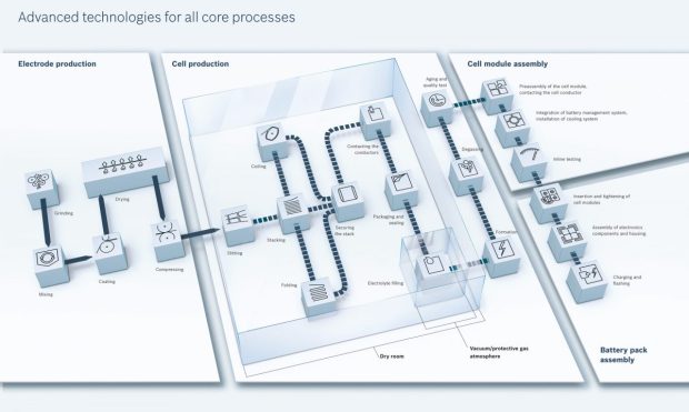
Layout of a battery production facility. Each individual step requires a great deal of highly efficient, flexible automation technology.
High-speed coating of electrodes…
Rechargeable battery cells are manufactured in a variety of forms. Regardless of whether they are cylindrical, prismatic or in the form of a pouch cell, each new generation has specific production and automation requirements. In an effort to achieve greater capacity in an even smaller space, the electrode foils wrapped or folded inside them are becoming increasingly thin and their coating increasingly thick. Highly precise web handling is needed in order to achieve the process speed needed for mass production but without impairing quality. This in turn requires specific functions such as those provided by the Motion Logic Control (MLC) control software from Bosch Rexroth with its libraries. The system is based on the embedded control system XMand allows motion tasks with over 200 distributed axes with sub-micrometer accuracy. Easily parameterizable control algorithms such as speed, force and travel control together with synchronization allow quick engineering with minimal programming work.
Coating places huge demands on the production system as it has a significant influence over the properties, operating life and energy density of a battery.
… and structuring
As part of the high-precision roll-to-roll process, the two electrodes along with two separators are combined to produce a sandwich structure and, in the case of cylindrical batteries, are formed into a roll. For prismatic cells, they must be accurately stamped or cut using a laser and then stacked flat or folded in the form of a Z. In order to manufacture pouch cells, the electrode sections must be accurately cut, stacked and then welded. Because the stacking and welding are relatively time-consuming processes, they often lead to inconvenient delays in the overall process.
Production steps for various cell types requiring highly efficient roll-to-roll processes and flexible transport systems to prevent bottlenecks.
Flexible transport prevents bottlenecks
In order to prevent bottlenecks when manufacturing batteries, displays and other electronic products, Bosch Rexroth has developed the Flexible Transport System FTS. It is dimensioned according to the mass to be transported and transports the individual workpiece carriers independently of one another from station to station. As a result, maximum acceleration is possible at all times. The multi-product system can take on exact positioning tasks at the same time. Thanks to a more flexible layout, more time-consuming processes can be carried out in parallel, thus doubling productivity. With these new possibilities, the production of notebook and smartphone batteries could be increased by almost 200 percent without impairing the time to market.
With the Flexible Transport System (FTS), Bosch Rexroth prevents typical bottlenecks in battery, display and electronic production.
Producing battery packs quickly and stably
Before it is closed and sealed, the battery needs to be filled with electrolyte. It should be as full as possible so that only minimal spaces remain in the separator foam. Because the liquid is toxic, the process must be completed quickly in order to avoid contaminating the environment. The individual battery cells are then combined to form modules. Automated systems are also used to produce the housings for the battery packs in large numbers and with minimal waste. Solutions such as the IoT Gateway from Bosch Rexroth which collect sensor and control data and passes them on to cloud platforms or on-premises solutions for analysis and evaluation are ideal for monitoring process stability and making continual improvements.
Highly efficient, flexible module production
A typical battery pack is made up of several cells and a management/cooling system. In order for manufacturers to adapt their existing production lines quickly in the event of product changes or to react to changing batch sizes, they should standardize automation and handling and at the same time ensure adequate flexibility. Once again, the flexible FTS transport system is an option here. Thanks to its scalability for products weighing anything from 1 g to 2,000 kg, it is suitable even for large vehicle batteries.
Green processes: efficient energy use
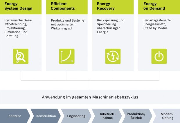
As an automation provider with expertise in a range of technologies and the ability to collect and analyze data from machines and systems quickly and easily, Bosch Rexroth helps machine manufacturers when it comes to green processes too. When used in battery production, the Rexroth 4EE (Rexroth for Energy Efficiency) system helps to increase productivity while conserving resources, cutting emissions and reducing operating costs. This is possible thanks to four levers which work throughout the life cycle:
Rexroth 4EE: The holistic view of machines and systems over their entire life cycle allows energy consumption, emissions and operating costs to be reduced sustainably while increasing productivity.
Productivity requirements demand full expertise
In spite of the various challenges in battery production, the situation from the point of view of an experienced automation partner is not new. The experts from Bosch Rexroth have already helped companies in the solar, photovoltaic and semiconductor industries to cope with the changes in their sectors and can therefore offer users and machine manufacturers competent advice. Over 20 years’ expertise from the printing industry has gone into the company’s roll-to-roll solutions. Open Core Engineering which allows the simulation and virtual commissioning of new automation solutions also plays a key role in reducing the time to market. Bosch Rexroth relies on open standards such as OPC UA in order to continually improve processes and provide condition-based maintenance. With innovative system solutions such as the FTS, global service and an international network of machine manufacturers, the basis for quick and lasting success in the market is already in place.
In addition to distribution, we design and fabricate complete engineered systems, including hydraulic power units, electrical control panels, pneumatic panels & aluminum framing. Our advanced components and system solutions are found in a wide variety of industrial applications such as wind energy, solar energy, process control and more.
Just when you thought the SmartLight was the most flexible Tower Indicator light ever, it gets even more flexible with the addition of a new mode. This new mode is appropriately named “Flexible Mode”. The new Flexible mode enables two new applications: User defined segments and Point-of-use indication.
User Defined Segments
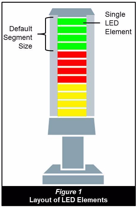
For traditional tower light applications, it’s now possible to define the segments as you see fit. It works by taking control of every LED element. Each SmartLight segment is comprised of four LED elements that can be controlled anyway you want (see Figure 1). For example, with the 3-segment SmartLight, you actually have 12 LED elements that you can organize any way you want. In Figure 2, we only use three LED elements per SmartLight segment, making it a four segment SmartLight. By using two LED elements we create six segments. Figure 3 is even more interesting, in this example we can see the size of the segments are sized by the intended users. Forklift Drivers need a larger light due to the distance and the fact that they are moving. Operators are closer than the forklift drivers, so their segment can be smaller, and maintenance can use the smallest segments because they are closest to the SmartLight when working on the machine.
Point of Use Indication
In these types of applications, the SmartLight is usedin close proximity, usually within the work envelope of the operators. In the example shown, the SmartLight is used in a socket tray application. The SmartLight indicates to the operator which socket is required for a specific task. Inductive proximity sensors connected to an IO-Link Hub verify the correct socket was pulled. The photo is showing an All-Call (all lights lit). Here you can see the unique LED element grouping only available with the new Flexible mode. Other applications for operator guidance are essentially endless. There are no technical limitations to your creativity.
The Flexible mode is available in all SmartLights with firmware version 3.0 or greater. So go have some fun!
In addition to distribution, we design and fabricate complete engineered systems, including hydraulic power units, electrical control panels, pneumatic panels & aluminum framing. Our advanced components and system solutions are found in a wide variety of industrial applications such as wind energy, solar energy, process control and more.
Control pumps have a fixed place in hydraulics. Your advantage: They only provide as much flow and/or power as is required for the specified movement task. But which pump control is suitable for which application? Mechanical-hydraulic or electro-hydraulic pump control? What are the differences?
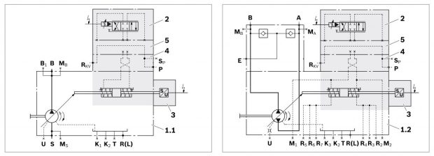
The advantages and disadvantages of the two pump control types can well be explained using the flow control of a deep drawing press as example. The hydraulic drive of the cylinder is based on a variable displacement pump working in an open circuit. The displacement is 250 cm3, the nominal pressure 350 bar. The mechanical input signal is hydraulically amplified. In this connection, the pump has three typical control tasks: Flow control (N and/or S function), power control (LR function) and pressure control (G function).
The mechanical input signal from the hand lever is hydraulically amplified. In this case, the flow is controlled by means of load-sensing. The pump swivel angle is adjusted independently of the load occurring at the actuator by means of a load sensing valve which is set to a Δp of 20 bar. So the velocity at the actuator remains constant.
The disadvantage: The throttling of the flow at the pump output goes along with a power loss which is completely converted into heat and increases the cooling demand. One advantage, however, is the easy set-up which does not even require a pilot oil pump as the adjustment energy is taken from the high pressure. Due to the continuous Δp of 20 bar, flow control is also possible at low pressures.
Power controllers increase the complexity
There is a need for an additional pilot oil pump if the deep drawing press – for example for safety-related reasons – requires a flow of zero in case of a low counter pressure (maximum of 4 bar). More components are necessary for realizing the power controller.
02) Electro-hydraulic pump control
Data recording and comparison by control electronics Compared to that, an electro-hydraulic system with only one fast high-response valve at the pump and amending control electronics is the more elegant solution. The regulated variables (path, force and velocity) correspond to the analog hydraulic variables flow and pressure.
The principle: A swivel angle sensor on the actuating piston and a separate and/or attached pressure transducer record the actual flow and pressure values. After comparison to the specified command values, the control performs all flow, pressure and torque limitation tasks and forwards a command value to the valve. Figure 2 shows different pump control systems which are autarkic subsystems and connected to the machine control via corresponding
interfaces.
Today, there is a whole range of motion controls and NC controls for hydraulic actuators available. It comprises single-axis controllers without control
cabinets where the electronic controls are integrated completely in the valve, up to multiple axis controllers with control cabinets for more complex tasks. In addition, intelligent pump controllers are improving the system performance. These control systems communicate via established field buses or Ethernet protocols with superior systems, and with these open standards it is possible to completely integrate them into Industry 4.0 architectures – this way, intelligent, networkable hydraulics are completely Industry 4.0 ready.
03) Decision-making aid: Selection of the pump control type
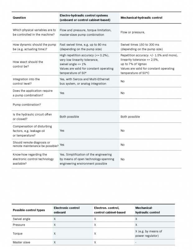
It first of all depends on the physical variable to be controlled whether the mechanical-hydraulic or the electro-hydraulic variant is finally the better choice for the relevant application. Flow and pressure can be controlled with both types. For limiting the torque, however, the mechanical-hydraulic method needs an additional power controller changing the flow with constant pressure and simultaneously increasing the complexity of the hydraulics. Here you can find the selction guide
Master-slave pump combinations
A master-slave pump combination interesting for many applications is only feasible with an electrohydraulic control; however, it allows for combined pump systems with special properties. If, for example, by an early swiveling out of the pump, the master pump provides a certain flow from a certain point in time, it can be positioned at the maximum swivel angle already upon start-up of the motor and deliver into the system, which again increases the velocity and precision of the application.
How dynamic and accurate should the pump be?
The required dynamics and precision are more decision-making criteria. If, for example, particularly high dynamics with up to 80 ms are required, a primarily controlled pump would be suitable. With regard to precision, electro-hydraulic control systems with a repetition accuracy of <= 0.2 % for the pressure and a linearity deviation for the swivel angle of <= 1 % show convincing results. Compared to that, mechanical-hydraulic controls achieve about +/- 1.5% repetition accuracy for the pressure and a linearity tolerance of 2.5 to 7 % of Vgmax. All values are valid for a constant operating temperature of 50°.
Conclusion
The strength of the mechanical-hydraulic pump control is its simplicity. It is, however, only convincing in correspondingly clear applications. With increasing requirements with regard to function, precision and energy efficiency, there is no alternative to electro-hydraulic control systems which allow for pressure and flow control with high control quality according to the demand. As digital control electronics with integrated Multi-Ethernet interface can moreover be integrated into most different structures, it moreover also masters the prerequisites for the increasingly demanded networking in the sense of Industry 4.0.
In addition to distribution, we design and fabricate complete engineered systems, including hydraulic power units, electrical control panels, pneumatic panels & aluminum framing. Our advanced components and system solutions are found in a wide variety of industrial applications such as wind energy, solar energy, process control and more.
In times of globalization and high labor costs it is a challenge to increase competitiveness in the fashion industry. Within a warehouse, an RFID system supports a high degree of automation as well as short transport distances. To supply dealers and to keep their facility profitable, one of the most successful fashion companies in the world has built a highly modern hanging garment distribution center. Let’s take a look at how they successfully implemented RFID technology to improve their processes.
Separate and sort clothes with just one hybrid module (2D code + RFID)
Within this distribution center 45,000 of these innovative clothes hanger adapters (L-VIS) are used. They replace the previous trolley-based logistics approach by allowing the transportation of a number of different garments that have the same destination.
With the investment in some additional space in the so-called buffer or storage zone, and by providing empty trolleys at various locations to keep the product flow moving, this project is successfully accomplished. A major advantage of this system, is the usability over the entire intralogistics chain. From receiving, to the hanging storage, to the sorter for single item identification, and from there as a transport unit to shipping.
The clothes hanger contains an RFID chip, that is automatically read by the conveying technology, and the 2D-code. This code is read manually by employees with a portable acquisition unit. The code can be DMC (Data Matrix Code), QR-Code, or any other optical code standard.
Information exchange without visual contact
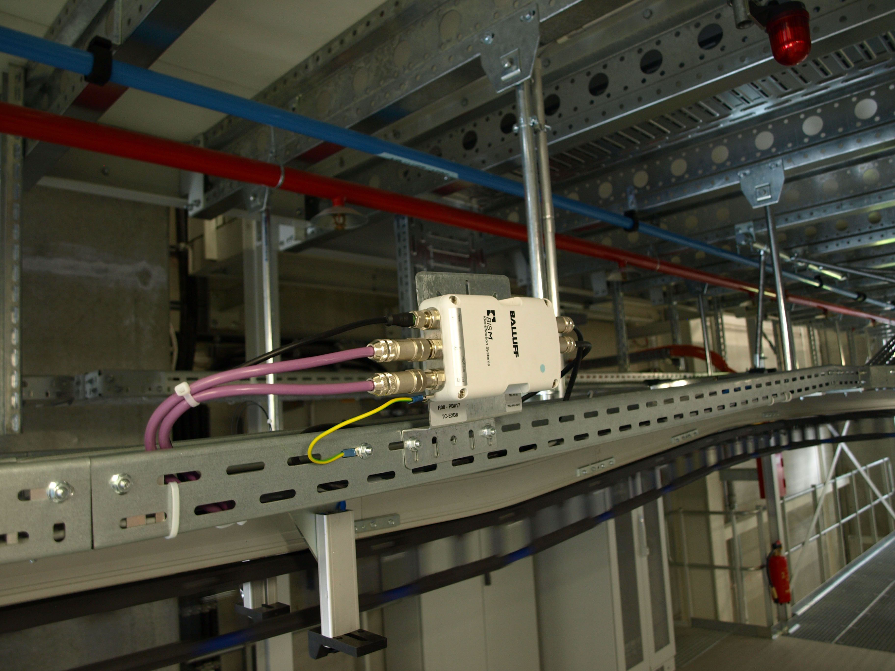
An RFID chip from the Balluff BIS-M series is installed. With this identification system, neither direct alignment nor contact is needed to enable data exchange via nearfield communication. Non-contact identification is extremely reliable and wear-free. The identification system consists of a rugged data carrier, a read/write head and an RFID processor unit. The processor unit communicates to the control system via Profibus. Other options available include ProfiNet, Ethernet-IP, etc.
The following table gives you an overview of which Radio Frequency Identification solutions are available at Balluff:
LF (BIS C)
LF (BIS L)
HF (BIS M)
UHF (BIS U)
Frequency
70/455 kHz
125 kHz
13.56 MHz
860 … 960 MHz
Short description
Dedicated solution to tool identification in Metal-Working industry.
Standard solutions for simple Track & Trace applications.
Fast & reliable – even with high volumes of data in medium distances in assembly, production and intralogistics.
Identification at large distances and bunching capability for current material flow concept.
For the customer, the decision to choose Balluff’s BIS-M system among others was the separation between the processor and read/write head. In a widespread facility it would not make sense to have a decoder with 30 read/write heads attached. By interfacing two read/write heads per processor it is possible to track the travel of a transport unit over the entire conveyor line as well as track within the aisles between the individual shelves. With the new BIS-V generation of RFID processors, even 4 read/write heads per processor can be connected.
Convincing product and support
An additional advantage of the BIS system is the compactness of its electronics. The L-VIS and the 30 mm read/write head are an ideal match. The simple mounting of the processors and ready-to-use connection persuaded the system integrators, in addition to the fact that the technology was already perfected and operated flawlessly. In the sorting area, the 2D code was supplemented by the RFID tags to reach speeds of up to 0.6 and 0.7 m/s. This would probably not have been possible with the installation of a corresponding camera technology.
Experiences have shown, that RFID projects need a lot of support. Consultation and assistance from true experts can be provided by the Balluff team. Get to know Balluff at www.balluff.com
In addition to distribution, we design and fabricate complete engineered systems, including hydraulic power units, electrical control panels, pneumatic panels & aluminum framing. Our advanced components and system solutions are found in a wide variety of industrial applications such as wind energy, solar energy, process control and more.
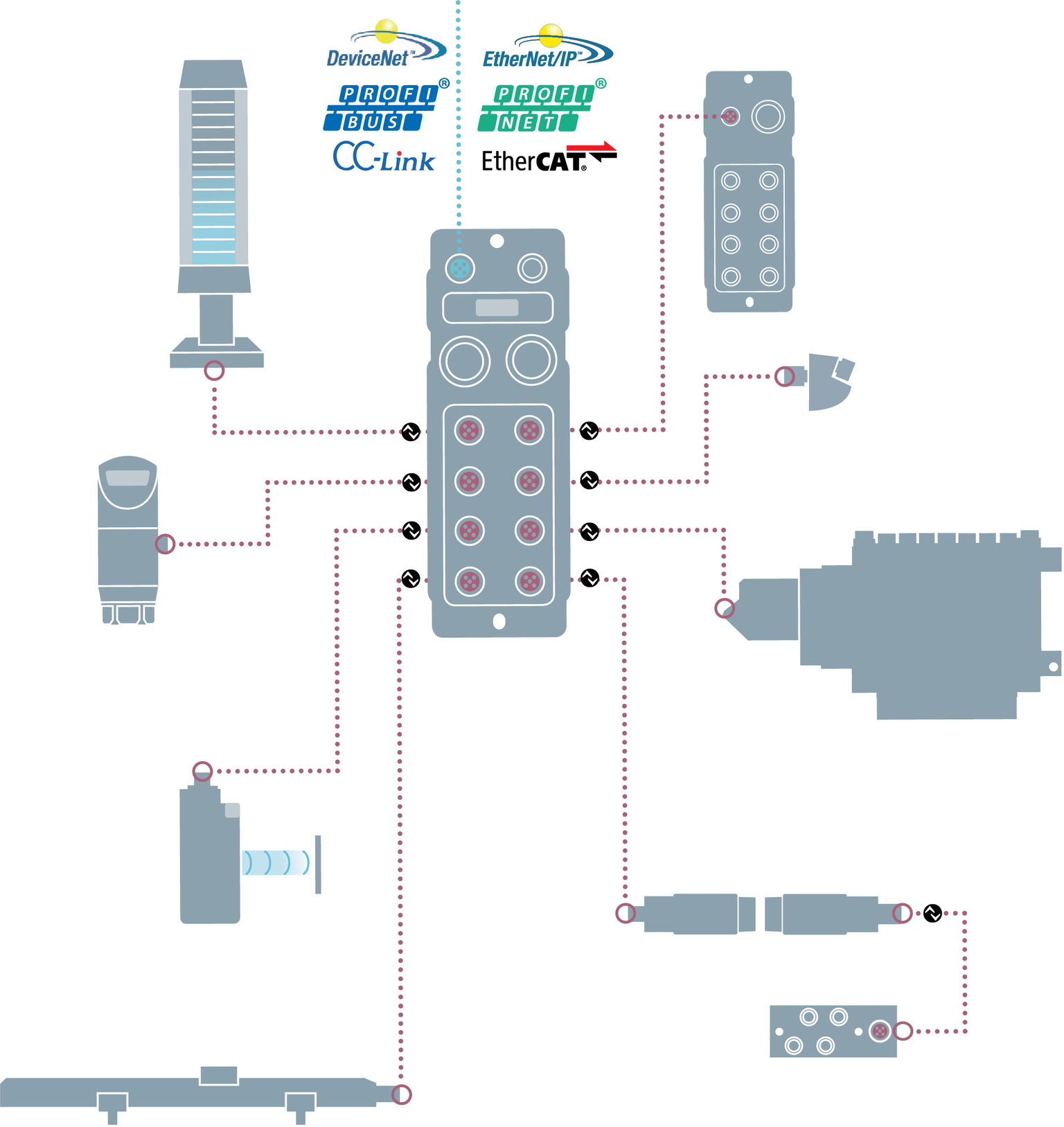
With the demands for flexible manufacturing, efficient production & visibility in our factories, smart manufacturing is driving the way we work today. Analytics and diagnostics are becoming critical to our ability to perform predictive maintenance, improve equipment effectiveness and monitor the condition of the machine as well as the components inside the machine. Typically, our first reaction is to put these devices onto Ethernet. However, the implementation of Ethernet requires a high skill set that is scarce in our traditional manufacturers today. Due to the simple control architecture of IO-Link devices, it allows for many Smart devices to provide the data we need for analytics with a reduction in the Ethernet skill set that has become a roadblock for many manufacturers.
Many people think IO-Link is a new industrial network to compete with EtherNet/IP or Profinet, but this is a common misconception. IO-Link is complementary to those networks and typically enables those networks to do even more than previously thought.
Open Standard
IO-Link is an open standard designed with the idea to act like USB for industrial automation. IO-Link is meant to simplify the smart sensor & intelligent device connectivity on the factory floor in a similar way that USB simplified connectivity to computers for auxiliary devices. IO-Link is not an industrial network or fieldbus; it is an industrial network and industrial controller agnostic. Designed with a master to slave configuration, addressing of the devices is point-to-point, similar to USB. Compatible IO-Link masters can act as slaves or nodes on a variety of industrial protocols and act complementary to the network of the user’s choosing. Eliminating the need for serial communication configuration or network addressing simplifies the connection and integration of devices.
Value in Machine Builds
IO-Link has advantages for both machine builders and discrete manufacturers. For machine builders, the biggest advantage comes from the simplified wiring scheme of IO-Link devices. We have seen machine builder users of IO-Link reduce their wiring hardware & labor costs by 30%-60% for sensors,
outputs & controls. This is realized with the simple sensor tool cords used for connections, quick-disconnect connectors on the cables and machine mount Ethernet masters devices. It is also realized for machine builders in an increase of turns on their floor, a reduction in build labor and significantly faster commissioning time.
Value on the Production Floor
For discrete manufacturers, the biggest advantages have come from the parameterization and diagnostic features on the IO-Link devices. With the ability to store & send parameters between the master & slave, IO-Link devices can be automatically configured. Hot-swapping a complex smart device like a pressure sensor can go from a stressful ordeal including 14-plus setpoints to literally a push of one button. Combining this functionality with multiple diagnostics both in the master & slaves eliminates human error and dramatically reduces downtime & troubleshooting for manufacturers.
To learn more about market leading IO-Link technologies, visit www.balluff.com.
In addition to distribution, we design and fabricate complete engineered systems, including hydraulic power units, electrical control panels, pneumatic panels & aluminum framing. Our advanced components and system solutions are found in a wide variety of industrial applications such as wind energy, solar energy, process control and more.
In many industries, especially in Packaging, the need to minimize capital equipment costs drives engineers to implement low-cost, manual methods of size change (also called format change) on their machinery. In most cases, this means hand-driven cranks with mechanical dial pointers and/or mechanical revolution counters.
While cost is saved on the procurement side, cost is also shifted over to the operational side. Plant management is left with the task of keeping accurate records of various machine set-ups needed to run different products, as well as the task of training machine operators to perform all machine set-ups correctly. It doesn’t always go as smoothly as expected, and machine reformatting can result in longer downtime than planned, machine stoppages, and possibly excessive scrap.
The key to size-change improvement is capturing the linear movements of the machine components and bringing them into the control system, and then providing “smart” visual feedback to the machine operator during setup. For capturing machine position, a robust and cost-effective magnetic linear encoder is ideal. However, traditional linear encoders deliver an A-B quadrature incremental signal, which requires re-homing upon start-up or after a power loss. What’s needed is an absolute encoder signal, but that brings other challenges such as the cost and complexity of implementing an absolute signal like SSI (Synchronous Serial Interface).
Fortunately, there’s a new encoder interface option that eliminates the problem of non-absolute feedback and the hassle of absolute position signal interface: IO-Link. IO-Link is a multi-vendor, non-proprietary, device-level serial digital interface that can be aggregated onto today’s Ethernet industrial networks. Magnetic linear encoders are now available that feature absolute position indication combined with the ease and convenience of the IO-Link communication protocol.
Now we just need to provide visual feedback to the machine operator regarding which direction and how far to turn the hand cranks. Once again, IO-Link provides the answer in the form of an IO-Link-enabled, fully programmable multi-segment LED stack light. When a new machine set up is required, the position parameters are stored in the controller. The controller communicates over IO-Link to the LED stack lights, indicating to the operator which dials need to be turned and in which direction. For example, a horizontally mounted stack light could be lit red on the right half, indicating that the dial needs to be turned to the right. As the position moves closer to the proper setting, the red segments count down until the entire stack light goes green, indicating that the correct position for that axis has been reached. No paper records to maintain and store, and very little training required with the intuitive operator visualization.
For more information about IO-Link linear encoders click here, and to learn more about IO-Link programmable LED stack lights visit www.balluff.com.
In addition to distribution, we design and fabricate complete engineered systems, including hydraulic power units, electrical control panels, pneumatic panels & aluminum framing. Our advanced components and system solutions are found in a wide variety of industrial applications such as wind energy, solar energy, process control and more.
In industrial distance and position measurement applications, one size definitely does not fit all. Depending on the application, the position or distance to be measured can range from just a few millimeters up to dozens of meters. No single industrial sensor technology is capable of meeting these diverse requirements.
Fortunately, machine builders, OEM’s and end-users can now choose from a wide variety of IO-Link distance and position measurement sensors to suit nearly any requirement. In this article, we’ll do a quick rundown of some of the more popular IO-Link measurement sensor types.
These sensors, available in tubular and block style form factors are used to measure very short distances, typically in the 1…5 mm range. The operating principle is similar to a standard on/off inductive proximity sensor. However, instead of discrete on/off operation, the distance from the face of the sensor to a steel target is expressed as a continuously variable value. Their extremely small size makes them ideal for applications in confined spaces.
Inductive Linear Position Sensors
Inductive linear position sensors are available in several block style form factors, and are used for position measurement over stroke lengths up to about 135 mm. These types of sensors use an array of inductive coils to accurately measure the position of a metal target. Compact form factors and low stroke-to-overall length factor make them well suited for application with limited space.
Magnetostrictive Linear Position Sensors
IO-Link Magnetostrictive linear position sensors are available in rod style form factors for hydraulic cylinder position feedback, and in external mount profile form factors for general factory automation position monitoring applications. These sensors use time-proven, non-contact magnetostrictive technology to provide accurate, absolute position feedback over stroke lengths up to 4.8 meters.
Laser Optical Distance Sensors
Laser distance sensors use either a time-of-flight measuring principle (for long range) or triangulation measuring principle (for shorter range) to precisely measure sensor to target distance from up to 6 meters away. Laser distance sensors are especially useful in applications where the sensor must be located away from the target to be measured.
Magnetic Linear Encoders
IO-Link magnetic linear encoders use an absolute-codedflexible magnet tape and a compact sensing head to provide extremely accurate position, absolute position feedback over stroke lengths up to 8 meters. Flexible installation, compact overall size, and extremely fast response time make magnetic linear encoders an excellent choice for demanding, fast moving applications.
IO-Link Measurement Sensor Trends
The proliferation of available IO-Link measurement sensors is made possible, in large part, due to the implementation of IO-Link specification 1.1, which allows faster data transmission and parameter server functionality. The higher data transfer speed is especially important for measurement sensors because continuous distance or position values require much more data compared to discrete on/off data. The server parameter function allows device settings to be stored in the sensor and backed up in the IO-Link master. That means that a sensor can be replaced, and all relevant settings can be downloaded from master to sensor automatically.
To learn about IO-Link in general and IO-Link measurement sensors in particular, visit www.balluff.com.
In addition to distribution, we design and fabricate complete engineered systems, including hydraulic power units, electrical control panels, pneumatic panels & aluminum framing. Our advanced components and system solutions are found in a wide variety of industrial applications such as wind energy, solar energy, process control and more.
I recently visited a customer that has a large amount of assembly lines where they have several machine builders manufacturing assembly process lines to their specification. This assembly plant has three different business units and unfortunately, they do not communicate very well with each other. Digging deeper into their error proofing solutions, we found an enormous amount of sensors and cables that could perform the same function, however they mandated different part numbers. This situation was making it very difficult for maintenance employees and machine operators to select the best sensor for the application at hand due to redundancy with their sensor inventory.
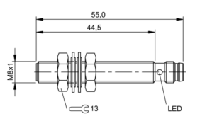
The customer had four different types of M08 Inductive Proximity sensors that all had the same operating specifications with different mechanical specifications. For example, one sensor had a 2mm shorter housing than one of the others in inventory. These 2mm would hardly have an effect when installed into an application 99% of the time. The customer also had other business units using NPN output polarity VS PNP polarity making it even more difficult to select the correct sensor and in some situations adding even more downtime when the employee tried to replace an NPN sensor where a PNP offering was needed. As we all know, the NPN sensor looks identical to the PNP offering just by looking at it. One would have to really understand the part number breakdown when selecting the sensor, and when a machine is down this sometimes can be overlooked. This is why it is so important to standardize on sensor selection when possible. This will result in more organized inventory by reducing part numbers, reducing efforts from purchasing and more importantly offering less confusion for the maintenance personel that keep production running.
Below are five examples of M08 Inductive sensors that all have the same operating specifications. You will notice the difference in housing lengths and connection types. You can see that there can be some confusion when selecting the best one for a broad range of application areas. For example, the housing lengths are just a few millimeters different. You can clearly see that one or two of these offerings could be installed into 99% of the application areas where M08 sensors are needed for machine or part position or simply error proofing a process.
For more information on standardizing your sensor selection visit www.balluff.com
In addition to distribution, we design and fabricate complete engineered systems, including hydraulic power units, electrical control panels, pneumatic panels & aluminum framing. Our advanced components and system solutions are found in a wide variety of industrial applications such as wind energy, solar energy, process control and more.
In many industries, especially in Packaging, the need to minimize capital equipment costs drives engineers to implement low-cost, manual methods of size change (also called format change) on their machinery. In most cases, this means hand-driven cranks with mechanical dial pointers and/or mechanical revolution counters.
While cost is saved on the procurement side, cost is also shifted over to the operational side. Plant management is left with the task of keeping accurate records of various machine set-ups needed to run different products, as well as the task of training machine operators to perform all machine set-ups correctly. It doesn’t always go as smoothly as expected, and machine reformatting can result in longer downtime than planned, machine stoppages, and possibly excessive scrap.
The key to size-change improvement is capturing the linear movements of the machine components and bringing them into the control system, and then providing “smart” visual feedback to the machine operator during setup. For capturing machine position, a robust and cost-effective magnetic linear encoder is ideal. However, traditional linear encoders deliver an A-B quadrature incremental signal, which requires re-homing upon start-up or after a power loss. What’s needed is an absolute encoder signal, but that brings other challenges such as the cost and complexity of implementing an absolute signal like SSI (Synchronous Serial Interface).
Fortunately, there’s a new encoder interface option that eliminates the problem of non-absolute feedback and the hassle of absolute position signal interface: IO-Link. IO-Link is a multi-vendor, non-proprietary, device-level serial digital interface that can be aggregated onto today’s Ethernet industrial networks. Magnetic linear encoders are now available that feature absolute position indication combined with the ease and convenience of the IO-Link communication protocol.
Now we just need to provide visual feedback to the machine operator regarding which direction and how far to turn the hand cranks. Once again, IO-Link provides the answer in the form of an IO-Link-enabled, fully programmable multi-segment LED stack light. When a new machine set up is required, the position parameters are stored in the controller. The controller communicates over IO-Link to the LED stack lights, indicating to the operator which dials need to be turned and in which direction. For example, a horizontally mounted stack light could be lit red on the right half, indicating that the dial needs to be turned to the right. As the position moves closer to the proper setting, the red segments count down until the entire stack light goes green, indicating that the correct position for that axis has been reached. No paper records to maintain and store, and very little training required with the intuitive operator visualization.
For more information about IO-Link linear encoders click here, and to learn more about IO-Link programmable LED stack lights visit www.balluff.com.
In addition to distribution, we design and fabricate complete engineered systems, including hydraulic power units, electrical control panels, pneumatic panels & aluminum framing. Our advanced components and system solutions are found in a wide variety of industrial applications such as wind energy, solar energy, process control and more.


 possible to define the segments as you see fit. It works by taking control of every LED element. Each SmartLight segment is comprised of four LED elements that can be controlled anyway you want (see Figure 1). For example, with the 3-segment SmartLight, you actually have 12 LED elements that you can organize any way you want. In Figure 2, we only use three LED elements per SmartLight segment, making it a four segment SmartLight. By using two LED elements we create six segments. Figure 3 is even more interesting, in this example we can see the size of the segments are sized by the intended users. Forklift Drivers need a larger light due to the distance and the fact that they are moving. Operators are closer than the forklift drivers, so their segment can be smaller, and maintenance can use the smallest segments because they are closest to the SmartLight when working on the machine.

 in close proximity, usually within the work envelope of the operators. In the example shown, the SmartLight is used in a socket tray application. The SmartLight indicates to the operator which socket is required for a specific task. Inductive proximity sensors connected to an IO-Link Hub verify the correct socket was pulled. The photo is showing an All-Call (all lights lit). Here you can see the unique LED element grouping only available with the new Flexible mode. Other applications for operator guidance are essentially endless. There are no technical limitations to your creativity.


 builders and discrete manufacturers. For machine builders, the biggest advantage comes from the simplified wiring scheme of IO-Link devices. We have seen machine builder users of IO-Link reduce their wiring hardware & labor costs by 30%-60% for sensors,
 option that eliminates the problem of non-absolute feedback and the hassle of absolute position signal interface: IO-Link. IO-Link is a multi-vendor, non-proprietary, device-level serial digital interface that can be aggregated onto today’s Ethernet industrial networks. Magnetic linear encoders are now available that feature absolute position indication combined with the ease and convenience of the IO-Link communication protocol.
 again, IO-Link provides the answer in the form of an IO-Link-enabled, fully programmable multi-segment LED stack light. When a new machine set up is required, the position parameters are stored in the controller. The controller communicates over IO-Link to the LED stack lights, indicating to the operator which dials need to be turned and in which direction. For example, a horizontally mounted stack light could be lit red on the right half, indicating that the dial needs to be turned to the right. As the position moves closer to the proper setting, the red segments count down until the entire stack light goes green, indicating that the correct position for that axis has been reached. No paper records to maintain and store, and very little training required with the intuitive operator visualization.
 style form factors are used to measure very short distances, typically in the 1…5 mm range. The operating principle is similar to a standard on/off inductive proximity sensor. However, instead of discrete on/off operation, the distance from the face of the sensor to a steel target is expressed as a continuously variable value. Their extremely small size makes them ideal for applications in confined spaces.


 Laser distance sensors use either a time-of-flight measuring principle (for long range) or triangulation measuring principle (for shorter range) to precisely measure sensor to target distance from up to 6 meters away. Laser distance sensors are especially useful in applications where the sensor must be located away from the target to be measured.
 flexible magnet tape and a compact sensing head to provide extremely accurate position, absolute position feedback over stroke lengths up to 8 meters. Flexible installation, compact overall size, and extremely fast response time make magnetic linear encoders an excellent choice for demanding, fast moving applications.