Guest contributor: Manfred Munzl for Balluff
Automation in Steel-Plants
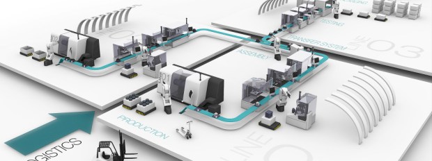
 Modern production requires a very high level of automation. One big benefit of fully automated plants and processes is the reduction of faults and mishaps that may lead to highly expensive downtime. In large steel plants there are hundreds of red hot steel slabs moving around, being processed, milled and manufactured into various products such as wires, coils and bars. Keeping track of these objects is of utmost importance to ensure a smooth and cost efficient production. A blockage or damage of a production line usually leads to an unexpected downtime and it takes hours to be rectified and restart the process.
To meet the challenges of the manufacturing processes in modern steel plants you need to control and monitor automatically material flows. This applies especially the path of the workpieces through the plant (as components of the product to be manufactured) and will be placed also at locations with limited access or hazardous areas within the factory.
Detection of Hot Metal
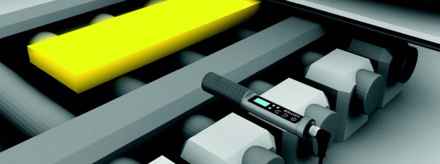
Standard sensors such as inductive or photoelectric devices cannot be used near red hot objects as they either would be damaged by the heat or would be overloaded with the tremendous infrared radiation emitted by the object. However, there is a sensing principle that uses this infrared radiation to detect the hot object and even gives a clue about its temperature.
 Non-contact infrared thermometers meet the requirements and are successfully used in this kind of application. They can be mounted away from the hot object so they are not destroyed by the heat, yet they capture the Infrared emitted as this radiation travels virtually unlimited. Moreover, the wavelength and intensity of the radiation can be evaluated to allow for a pretty accurate temperature reading of the object. Still there are certain parameters to be set or taught to make the device work correctly. As many of these infrared thermometers are placed in hazardous or inaccessible places, a parametrization or adjustment directly at the device is often difficult or even impossible. Therefore, an intelligent interface is required both to monitor and read out data generated by the sensor and – even more important – to download parameters and other data to the sensor.
Technical basics of Infrared Hot-Metal-Detectors
Traditional photoelectric sensors generate a signal and receive in most cases a reflection of this signal. Contrary to this, an infrared sensor does not emit any signal. The physical basics of an infrared sensor is to detect infrared radiation which is emitted by any object.
Each body, with a temperature above absolute zero (-273.15°C or −459.67 °F) emits an
electromagnetic radiation from its surface, which is proportional to its intrinsic
temperature. This radiation is called temperature or heat radiation.
By use of different technologies, such as photodiodes or thermopiles, this radiation can be detected and measured over a long distance.
Key Advantages of Infrared Thermometry
This non-contact, optical-based measuring method offers various advantages over thermometers with direct contact:
- Reactionless measurement, i.e. the measured object remains unaffected, making it possible to measure the temperature of very small parts
- Very fast measuring frequence
- Measurement over long distances is possible, measuring device can be located outside the hazardous area
- Very hot temperatures can be measured
- Object detection of very hot parts: pyrometers can be used for object detection of very hot parts where conventional optical sensors are limited by the high infrared radiation
- Measurement of moving objects is possible
- No wear at the measuring point
- Non-hazardous measurement of electrically live parts
IO-Link for smarter sensors
![]() IO-Link as sensor interface has been established for nearly all sensor types in the past 10 years. It is a standardized uniform interface for sensors and actuators irrespective of their complexity. They provide consistent communication between devices and the control system/HMI. It also allows for a dynamic change of sensor parameters by the controller or the operator on the HMI thus reducing downtimes for product changeovers. If a device needs to be replaced there is automatic parameter reassignment as soon as the new device has been installed and connected. This too reduces manual intervention and prevents incorrect settings. No special device-proprietary software is needed and wiring is easy, using three wire standard cables without any need for shielding.
IO-Link as sensor interface has been established for nearly all sensor types in the past 10 years. It is a standardized uniform interface for sensors and actuators irrespective of their complexity. They provide consistent communication between devices and the control system/HMI. It also allows for a dynamic change of sensor parameters by the controller or the operator on the HMI thus reducing downtimes for product changeovers. If a device needs to be replaced there is automatic parameter reassignment as soon as the new device has been installed and connected. This too reduces manual intervention and prevents incorrect settings. No special device-proprietary software is needed and wiring is easy, using three wire standard cables without any need for shielding.
Therefore, IO-Link is the ideal interface for a non-contact temperature sensor.
All values and data generated within the temperature sensor can be uploaded to the control system and can be used for condition monitoring and preventive maintenance purposes. As steel plants need to know in-process data to maintain a constant high quality of their products, sensors that provide more data than just a binary signal will generate extra benefit for a reliable, smooth production in the Industry 4.0 realm.
To learn more about this technology visit www.balluff.com.
![]() CMA/Flodyne/Hydradyne is an authorized Balluff distributor in Illinois, Wisconsin, Iowa and Northern Indiana.
CMA/Flodyne/Hydradyne is an authorized Balluff distributor in Illinois, Wisconsin, Iowa and Northern Indiana.
In addition to distribution, we design and fabricate complete engineered systems, including hydraulic power units, electrical control panels, pneumatic panels & aluminum framing. Our advanced components and system solutions are found in a wide variety of industrial applications such as wind energy, solar energy, process control and more.


 = 2.74 lb-ft or 3.715_Nm (1.35582_Nm/lb-ft.)