Photoelectric sensors with laser and red-light are widely used in all areas of industrial automation. A clean, dust-free and dry environment is usually essential for the proper operation of photoeyes, however, they can be the best choice in many dirty and harsh applications. Examples of this are raw steel production in steel mills and further metallurgical processes down to casting and hot-rolling.
Cutting of billets at casting – Photo: M.Münzl
Photoelectric sensors are especially useful in these environments thanks to their long sensing distance and their ability to detect objects independent of their material.
Most photoelectric sensors are approved to work in ambient temperatures of 55 to 60 °C. The maximum temperature range of these sensors is most often limited by the specifications of the optical components of the sensor, like the laser-diodes, but by taking certain precautions photoelectric sensors can provide optimal use in much hotter applications.
Maximize the distance In steel production many parts of the process are accompanied by high ambient temperatures. Liquid steel and iron have temperatures from 1400 to 1536 °C. Material temperature during continuous casting and hot-rolling are lower but still between 650 and 1250°C.
The impact of heat emission on the sensors can be reduced significantly by placing the sensor as far from the target object as possible, something you can’t do with inductive sensors which have a short range. Very often the remote mounting will allow the sensor to operate at room temperature.
If you intend to detect quite small objects with high precision, the maximum distance for the installation might be limited. For this purpose chemical resistant glass fibers are suitable and can handle temperatures up to 250 °C. These pre-fabricated fiber optic assemblies can be easily attached to the sensor. The sensor itself can be mounted on a cooler and protected place.
Detect Glowing Metals If you want to reliably detect red-hot or white glowing steel parts with temperatures beyond 700 °C, you won’t be able to use standard laser or red-light sensors. Red-hot steel emits light at the same wavelength that it is used by photoelectric sensors. This can interfere with the function of the sensor. In such applications you need to use sensors which operate based on infrared light.
Add Protection
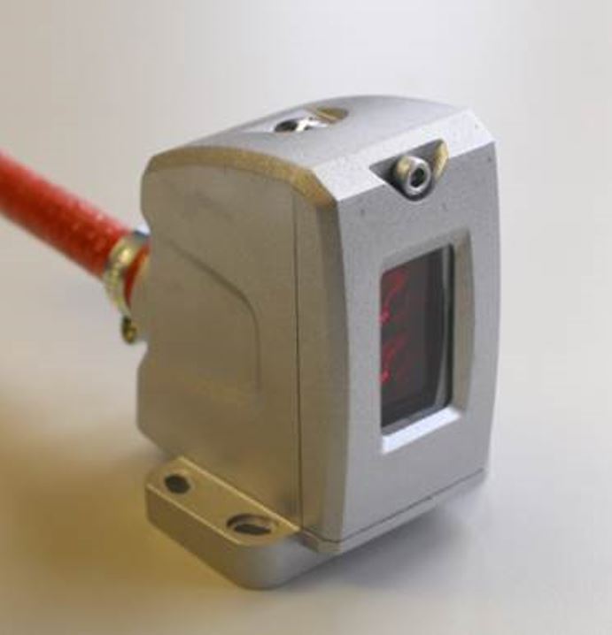
Sensor enclosure and protective cable sleeve
At many locations in the steel production process, the extensive heat is only temporary. In a hot rolling mill, a slab runs through a rougher mill multiple times before it continues to a multi-stage finishing mill stand to be rolled to the final thickness. After that the metal strip runs into the coiler to be winded up.
This process runs in sequence, and the glowing material is only present at each stage of production for a short time. Until a new slab runs out of the reheating furnace, temperatures normalize.
Standard sensors can work in these conditions, but you do run the risk of even temporary temperature hikes causing sensor failure and then dreaded downtime. To protect photoelectric sensors against temporary overheating, you can use a protective enclosure. These can provide mechanical and thermal protection to the sensors which often have plastic bodies. Additional protection can be achieved when a heat resistant sleeve is used around the cable.
Photoelectric sensors do have their limits and are not suitable for all applications, even when precautions are taken. Ask yourself these questions when deciding if they can be the right solution for your high temperature applications.
Which distance between the hot object and sensor can be realized?
What is the maximum temperature at this location?
How long will the sensor be exposed to the highest heat levels during normal operation and at breakdown?
In addition to distribution, we design and fabricate complete engineered systems, including hydraulic power units, electrical control panels, pneumatic panels & aluminum framing. Our advanced components and system solutions are found in a wide variety of industrial applications such as wind energy, solar energy, process control and more.
The complexity of factory automation creates constant challenges which drive innovation in the industry. One of these challenges involves the ability to accurately detect the presence of shiny or highly reflective objects. This is a common challenge faced in a variety of applications, from sensing wheels in an automotive facility to detecting an aluminum can for filling purposes at a beverage plant. However, thanks to advancements in photoelectric sensing technologies, there is a reliable solution for those type of applications.
Why are highly reflective objects a challenge?
Light reflects from these types of objects in different directions, and with minimum energy loss. This can cause the receiver of a photoelectric sensor to be unable to differentiate between a signal received from the emitter or a signal received from a shiny object. In the case of a diffuse sensor, there is also the possibility that when trying to detect a shiny object, the light will reflect away from the receiver causing the sensor to ignore the target.
So how do we control the direction of the light going back to the receiver, and avoid false triggering from other light sources? The answer is in polarized retroreflective sensors.
Retroreflective sensors require a reflector which reflects the light back to the sensor allowing it to be captured by the receiver. This is achieved by incorporating sets of three mirrors oriented at right angles from each other (referred to as corner cubes). A light beam entering this system is reflected by all three surfaces and exits parallel to the incident beam. Additionally, corner cubes are said to be optically active as they rotate the plane of oscillation of the light by 90 degrees. This concept, along with polarization, allow this type of sensor to accurately detect shiny objects.
Polarization
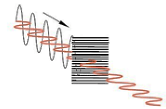
Light emitted by a regular light source oscillates in planes on dispersal axes. If the light meets a polarizing filter (fine line grid), only the light oscillating parallel to the grid is let through (see figure 1 below).
Figure 1
In polarized retroreflective sensors, a horizontal polarized filter is placed in front of the emitter and a vertical one in front of the receiver. By doing this, the transmitted light oscillates horizontally until it hits the reflector. The corner cubes of the reflector would then rotate the polarization direction by 90 degrees and reflect the light back to the sensor. This way, the returning light can pass through the vertical polarized filter on the receiver as shown below.
Figure 2
With the use of polarization and corner cubed reflectors, retroreflective sensors can create a closed light circuit which ensures that light detected by the receiver was sourced exclusively by the emitter. This creates a great solution for applications where highly reflective targets are influencing the accuracy of sensors or causing them to malfunction. By ensuring proper operation of photoelectric sensors, unplanned downtime can be avoided, and overall process efficiency can be improved.
In addition to distribution, we design and fabricate complete engineered systems, including hydraulic power units, electrical control panels, pneumatic panels & aluminum framing. Our advanced components and system solutions are found in a wide variety of industrial applications such as wind energy, solar energy, process control and more.
It is not a surprise that optimizing yield is one of the most important objectives in a sawmill (or lumber mill) as it is in any other industry. The big difference is that there is hardly any control over the quality of the logs that enter the sawill. In the ideal world all logs are not only cylindrical in shape but also straight. But obviously each individual log is unique in shape. Crooked, out-of-round, or tapered logs are common and even worse: usually it is a combination of these shapes.
Still the target is to recover as much yield from each log as possible. Therefore sawmills turn into highly automated factories with three dimensional (3D) measurement of logs, and advanced equipment for primary and secondary breakdown. Basically there are three areas of automation in a sawmill:
3D measurement for optimum cutting pattern to recover most yield from a log
Automation of drives to position the log itself, or tools (e.g. sawblades, knifes, canter heads…) at high velocity to increase throughput
Automation of log and lumber handling to minimize the gap between the logs
All of the three areas support the sawmill’s target to get the most out of the logs at the highest speed. The worst case is any downtime as it directly impacts the whole log to lumber process. Therefore electrical engineers look for sensors that meet the challenges of the sawmill environment. Mainly sensors must meet high vibration and shock standards. As they are exposed to the environment, protective housings help to protect the sensors from logs crashing into them.
From logs to lumber
Wave feeder with analog distance sensor
To efficiently process logs to lumber, sawmills use dedicated equipment for different sizes of logs. As a result bigger mills have a primary and a secondary breakdown area. Independent from the logs, sawmills aim to minimize the gaps and to avoid changes in the setup. This allows them to run faster and to increase the production rate. Here is the process how a log turns into lumber in a sawmill.
When a log arrives at the mill it is indexed onto the infeed conveyer (could be a step feeder or log loader). Either inductive sensors sequence the steps. Or a magnetostrictive position sensor (linear transducer) provides feedback of the step position of the loader to control motion and speed. Once the log is on the loader analog distance sensors determine the distance to the end of the log from the side of the loader wall.
This is to ensure a constant distance between the logs (log gap) as they enter the sawmill. Knowing the distance enables them to control when the log is loaded on the conveyor. And thereby they can control the gap. As an alternative photoelectric a thru beam sensor determines if a log is present for the final two steps on a loader. These sensors work with a long measuring range. Additionally they have a large functional reserve and are very resistant to dirt and dust.
Primary breakdown – from raw log to slabs and cants
The first step of the log is to run through a debarker that removes the bark. As there are tolerances in shape, linear transducers and photoelectric analog distance sensors are used to determine log sizes. These sizes help to adjust the debarker’s pressure and speed. After debarking the logs are cut to the best pre-determined length by cut-off or bucking saws. Again linear transducers are used to control the motion of the cut-off saw swing.
By stacking some photoelectric through beam sensors they can be used to determine the log diameter roughly. This leads to increasing speed as the saw can cut through smaller logs faster and has to slow down for larger logs. Many mills just sort their debarked logs into “large logs” and “small logs” based on their diameters. And then go into machines that are set up for those particular log sizes.
Log carriage for 20″ (50cm) logs and more
Carriage saw with BTL for positioning
Many mills also run a lot of larger logs and therefore have a log carriage. This is a single band saw with a carriage that runs on railway style tracks. The carriage has three or four knees that have positioners and log clamps (dogs) that hold the log. In the knees hydraulic cylinders with magnetostrictive transducers position the log. Even under extreme surrounding conditions, these position sensors guarantee a high machine and system availability. The clamps hold the log while it movesthrough the band saw. The carriage cuts the logs into slabs (two flat, two rounded sides) or into cants (four flat, square sides).
Secondary Breakdown – from small logs, slabs and cants to lumber
Mills that run smaller logs do not have to break down the logs prior to putting them through the secondary breakdown equipment. After the cut-off saw, the small logs will be sorted by size into bins. Step feeders index them again onto a conveyor and that feeds them through a Scanner into the small log line machine. To recover as much yield as possible log turners turn the logs in the optimum position. Chipper canters center them to enable curve sawing, which leads to increased lumber recovery.
Hydraulic drives dominate small log lines and all motion control happens with linear position transducers. Typical small log lines consist of log turning and centering, chipping with canter heads, saw box slew and skew, saw box positioniers, profiling heads and outfeed pickers. All of the equipments’ design aims for speed and therefore they require fast and accurate position feedback. Sensors and transducers must withstand high shock and vibration. Balluff’s products survive even in toughtest environments and undergo intensive shock and vibration testing.
Shifting edgers and curve sawing
Sawblade Adjustment with BTL
Gang edgers and shifting edgers cut cants and slabs from the primary breakdown into boards. Gang edgers have circular saws stacked at fixed spacing. Shifting edgers look similar to gang edgers except that they change spacing between saw blades can be changed. Therefore each saw is connected to a hydraulic positioner. A scanner looks at the cant or slab and determines the best solutions of cuts to produce best results. After the scanner the positioners of the shifting edgers set the new saw spacing to match that solution.
Edger optimizers pre-position the board and optimize the infeed to get the best payback from the machine. Photoelectric (laser) retroreflective sensors track boards through the ducker table. The infeed position cylinder (with integrated linear transducer) skews the board in the best position to be fed in the edger.
Trimming, sorting, stacking, strapping, shipping
Photoelectric sensors detect boards at the trimmer infeed
The boards go into bins when they come out of the edgers. Another scanner determines if the board can be cut down into shorter boards. Or if a damaged end needs to be cut off so that the board is not graded lower. The next step is processing the board through a trimmer. The trimmer is a set of up to about a dozen circular saws positioned across the conveyor. It can cut longer boards down into two or three shorter boards or just trim the ends.
Photoelectric analog distance sensors detect stacked boards from high distance
Background suppression photoelectric sensors at the indeed of the trimmer look down at the board as it goes into the machine. And they determine if the board is actually as long as the scanner information indicates. The same sensors confirm after the trimmer that the board was cut down to the proper size. After the trimmer they go into a sorter and and from there to stacking and strapping to final shipment.
We provide additional information how our sensors help to automate sawmills on our website.
Veneer instead of solid wood
A sawmill produces solid wood. This means that the board is out of one piece of wood. Another type of boards is veneer. This means that thin layers of wood are glued together to reach a board. Usually these layers are less that 3 mm thick. A lathe continuously turns a log against a blade to peel it. With each rotation the log becomes thinner. Therefore the blade position needs to be adjusted. Hydraulic cylinders with integrated linear transducers centerthe log and position the blade to peel the trunk. The thin layers are glued together in a veneer press.
Not only stationary, but also portable sawmills
In the end our sensors and transducers not only help to automate huge mills, but also portable sawmills. Magnetostrictive or magnetically sensors enable operators to exactly position the saw unit. So they achieve accurate and fast cutting of boards. Wood-Mizer is a world leading supplier of efficient and fast portable sawmills that uses magnetostrive position sensors in it’s machines. The reasons for Balluff are its product and service quality as well as the availability.
In addition to distribution, we design and fabricate complete engineered systems, including hydraulic power units, electrical control panels, pneumatic panels & aluminum framing. Our advanced components and system solutions are found in a wide variety of industrial applications such as wind energy, solar energy, process control and more.
Photoelectric sensors have been around for a long time and have made huge advancements in technology since the 1970’s. We have gone from incandescent bulbs to modulated LED’s in red light, infrared and laser outputs. Today we have multiple sensing modes like through-beam, diffuse, background suppression, retroreflective, luminescence, distance measuring and the list goes on and on. The outputs of the sensors have made leaps from relays to PNP, NPN, PNP/NPN, analog, push/pull, triac, to having timers and counters and now they can communicate on networks.
The ability of the sensor to communicate on a network such as IO-Link is now enabling sensors to be smarter and provide more and more information. The information provided can tell us the health of the sensor, for example, whether it needs re-alignment to provide us better diagnostics information to make troubleshooting faster thus reducing downtimes. In addition, we can now distribute I/O over longer distances and configure just the right amount of IO in the required space on the machine reducing installation time.
IO-Link networks enable quick error free replacement of sensors that have failed or have been damaged. If a sensor fails, the network has the ability to download the operating parameters to the sensor without the need of a programming device.
With all of these advancements in sensor technology why do we still have different sensors for each sensing mode? Why can’t we have one sensor with one part number that would be completely configurable?
Just think of the possibilities of a single part number that could be configured for any of the basic sensing modes of through-beam, retroreflective, background suppression and diffuse. To be able to go from 30 or more part numbers to one part would save OEM’s end users a tremendous amount of money in spares. To be able to change the sensing mode on the fly and download the required parameters for a changing process or format change. Even the ability to teach the sensing switch points on the fly, change the hysteresis, have variable counter and time delays. Just imagine the ability to get more advanced diagnostics like stress level (I would like that myself), lifetime, operating hours, LED power and so much more.
Obviously we could not have one sensor part number with all of the different light sources but to have a sensor with a light source that could be completely configurable would be phenomenal. Just think of the applications. Just think outside the box. Just imagine the possibilities. Let us know what your thoughts are.
To learn more about photoelectric sensors, visit www.balluff.com.
In addition to distribution, we design and fabricate complete engineered systems, including hydraulic power units, electrical control panels, pneumatic panels & aluminum framing. Our advanced components and system solutions are found in a wide variety of industrial applications such as wind energy, solar energy, process control and more.


 It is not a surprise that optimizing yield is one of the most important objectives in a sawmill (or


