Author: CMA/Flodyne/Hydradyne

Hydraulics Meets Internet of Things: Avoiding Machine Downtime the Intelligent Way

Guest Contributor: Luisa Franz, Bosch Rexroth


IoT-capable hydraulic power unit ensures efficient production

With the newly developed, intelligent CytroBox unit, Rexroth combines the benefits of hydraulics with low energy consumption and software-based functions. The integrated CytroConnect IoT service ensures higher availability and avoids unplanned downtimes. With this IoT service, operators can monitor operating statuses and plan maintenance in a cost-effective manner. As a result, fluid technology has taken a further step towards the factory of the future.

The digitalization of mechanical and plant engineering means more than decentralized intelligence, integrated sensors and connectivity. This applies to hydraulics too. With its power density and immunity to impacts and vibrations, hydraulics plays a central role as an important drive technology in Industry 4.0 too. The compact CytroBox unit is revolutionizing hydraulic pressure supply. CytroBox is a modular hydraulic power unit for the medium performance range from 7.5 kW to 30 kW. It comprises optimally tailored, impressively compact components. Compared to previous units, considerable amounts of space can be saved.

190304_BR_CytroBox_Produktstandbild.jpg

75% less oil

One of CytroBox’s unique selling points is it compactness. This is possible because the hydraulic power unit can be integrated into a factory like a control cabinet, i.e. upright. The tank no longer supports all other components – Rexroth developed a special supporting structure for this purpose. In addition, a degassing flow-optimized tank is used. On the basis of extensive CFD simulations, the developers improved the tank geometry so skillfully that the new unit needs only a quarter of the oil required by classic designs: instead of 600 liters, 150 liters are now enough – with at least the same service life. The drive unit – a component which usually takes up a large amount of space in hydraulic power units – is equally compact. The asynchronous servo motor has been replaced by a synchronous servo motor. This is the most efficient motor design, producing the same torque even though it is 80 to 90% smaller. The manifold too was redesigned: thanks to 3D printed sand cores, the block including the internal flow geometry is now cast. As a result of this flow-optimized inner structure, less material and space are required. Thanks to all these measures, the CytroBox has a footprint of just 0.5 square meters instead of one and a half to two square meters. This represents a saving of up to 75%. On top of this, there are energy savings of up to 80% as well as a 10 dB(A) reduction in noise emissions. As a result, noise emissions are lower than 75 dB(A).

Connected for the factory of the future

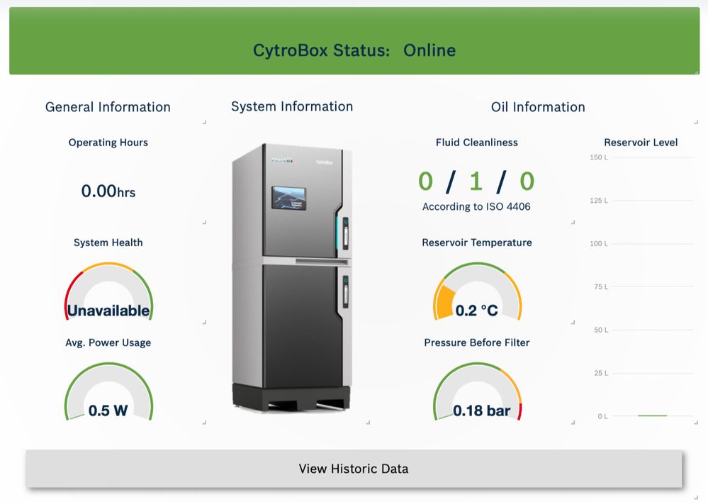
In the CytroBox, machine manufacturers will find a ready-configured drive controller with numerous integrated functions. Various sensors provide information on the current filter, oil or drive status. The collected sensor data are bundled via IO-LinkMaster and pre-processed by the drive controller so that they can be integrated flexibly into modern machine designs. This means that the CytroBox is IoT-ready.

CytroConnect_Monitor.jpg

CytroConnect Monitor

With the CytroConnect digital service, operators have all information regarding the CytroBox at their fingertips at all times – whether it be information regarding the standardized visualization of the component and operating status or chargeable IoT services such as forthcoming maintenance work and predictive maintenance analyses using Rexroth’s Online Diagnostics Network (ODiN).

The data collected are transferred to the browser-based CytroConnect Monitor web dashboard via Multi-Ethernet or 4G-LTE. As a result, operators can be kept up to date regarding the current operating status and key status indicators on any end device (tablet, smartphone, PC). This plug and play service is free of charge and can be used without additional installation work. CytroConnect is implemented in the CytroBox as standard.

Greater availability thanks to additional analysis functions

In addition to the CytroBox’s automatic status monitoring, maintenance personnel and maintenance managers can add extra solutions for various applications as add-ons. These pay-per-use payment models include additional IoT analysis tools and can be subscribed to on a monthly basis.

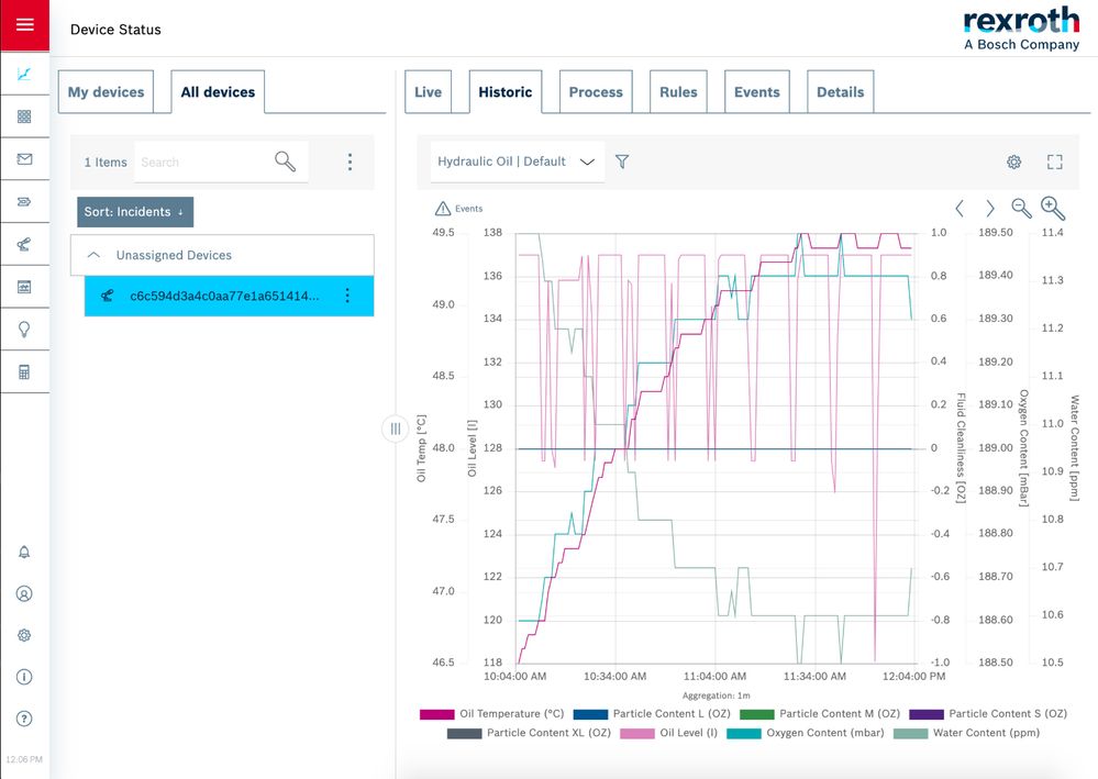
For optimizing maintenance processes, the CytroConnect Maintain module offers access to historical sensor data as well as messages if maintenance is required or in the event of critical operating statuses. Pre-defined and custom rules allow customers to improve their maintenance strategy on an ongoing basis. Customers benefit from scalable software solutions from the Bosch IoT portfolio such as the Nexeed Production Performance Manager and the integrated know-how of the Rexroth domain specialists. The Nexeed Production Performance Manager is a condition monitoring software solution for systematic production optimization.

CytroConnect_Addons.jpg

CytroConnect Maintain

With CytroConnect Maintain, data concerning the most important components for reliability and operating life (the hydraulic oil and the drive unit) are assessed. Comprehensive insights into the correlation between the speed of the servo motor and the flow allow the monitoring of system leakage, while correlations between motor data and the operating pressure allow conclusions regarding drive behavior. The leakage sensor, temperature and level sensor, particle sensor, water sensor and oxygen sensor are additional data sources which can be used to make a status diagnosis.

Planning predictive maintenance efficiently

A further add-on, CytroConnect Predict, uses the machine learning algorithms of the Rexroth Online Diagnostics Network (ODiN) for a predictive analysis of the system. With this IoT service, the power curves for a wide range of components are recorded for data analysis purposes. In the event of deviations, the system automatically calculates the expected remaining operating life of the relevant component and informs the operator immediately via a push message. As a result, predictive maintenance application cases can be taken into account predictively in the operator’s maintenance plans, thus ensuring maximum availability.

Conclusion

This new form of hydraulics is energy-efficient, quiet, space-saving and intelligent. With the integrated CytroConnect IoT service, the CytroBox offers anything from transparent, efficient machine monitoring to intelligent predictive maintenance measures. Thanks to the CytroBox, fluid technology is now one step closer to the factory of the future.

www.cytroconnect.com

www.boschrexroth.com/cytro


cropped-cmafh-logo-with-tagline-caps.pngCMA/Flodyne/Hydradyne is an authorized Bosch Rexroth distributor in Illinois, Wisconsin, Iowa and Northern Indiana.

In addition to distribution, we design and fabricate complete engineered systems, including hydraulic power units, electrical control panels, pneumatic panels & aluminum framing. Our advanced components and system solutions are found in a wide variety of industrial applications such as wind energy, solar energy, process control and more.

TIME IS MONEY: ENGINEERING FOR LARGE POWER UNITS REDUCED TO FIVE DAYS

Time and cost savings through standardization and proven designs

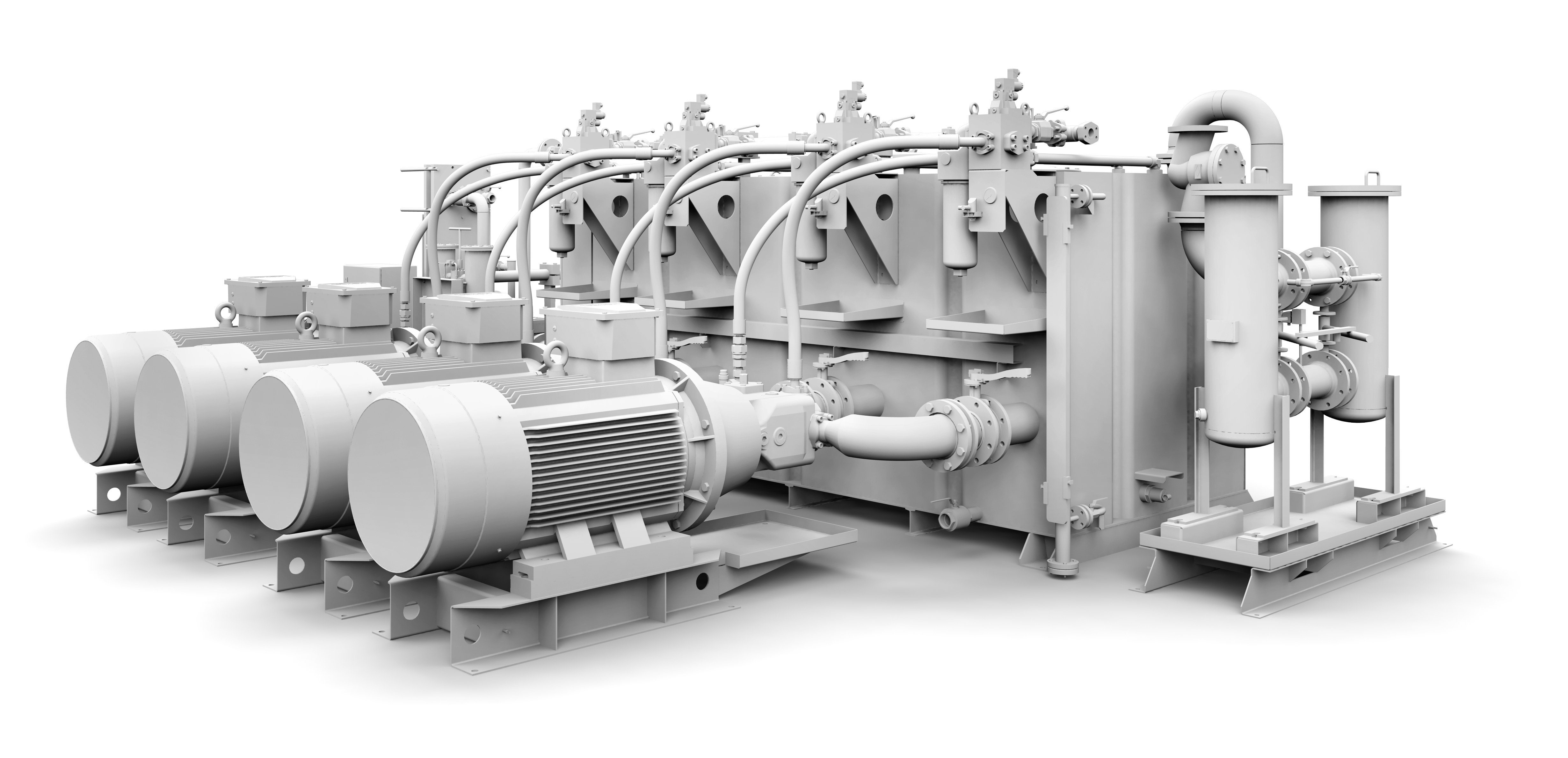
Faster, simpler, more productive and cost-effective: Rexroth’s new modular system called ABMAXX speeds up the engineering and commissioning of large hydraulic power units in projects designed to modernize existing systems or construct new ones. The hydraulics specialists are able to create a quote complete with a hydraulic circuit diagram, a parts list, a 3D model and dimensions all within a maximum of five working days. As such, system manufacturers and end users can reduce engineering lead times alone by 80 %. The pre-configured ABMAXX modules are composed of highly available standard components. The modular approach reduces costs by up to 35 % and increases operational availability.

When constructing new or modernizing existing steelworks and rolling mills, large-scale presses and test systems or the central media supply of factories, hydraulics is and will continue to be the key drive technology both now and in the future on account of its high power density, robustness and durability. Thanks to the wide range of components available, there is plenty of scope for designing tailored solutions. In the past, system manufacturers and major end users defined their own standards which they implemented with their own resources in development. In light of ever increasing cost pressure and a global shortage of qualified specialists, these days they are increasingly scrutinizing that approach. Their main goal is to achieve pressure and quantity as cost-effectively as possible.

This is where Bosch Rexroth’s modular system ABMAXX comes in. The company is the first hydraulics manufacturer to come up with a modular solution with which system manufacturers and end users can significantly reduce the complexity of engineering large power units for 24/7 operations. On the one hand, it enables them to take advantage of all the economic benefits of cross-manufacturer standardization yet, on the other hand, the modular design provides ample opportunity for coming up with application-specific solutions.

Three pressure ratings and five modules

The concept initially covers tank sizes ranging from 2,000 to 12,500 l. With its three pressure ratings, namely 160, 210 and 315 bar, the concept satisfies the trend for higher operating pressures, thus ensuring it will be fit for the future. Achievable flows currently range from 345 l/min to 2,160 l/min. These basic conditions meet the typical requirements of numerous large plants.

In order to transform the benefits of standardization into shorter project lead times, Rexroth has defined five modules: tank, pump block, circulation unit, cooling and filter unit, and safety controls. Each module is based on proven constructions with a tried-and-tested design. As such, Rexroth is able to considerably reduce the risk of initial errors in the construction.

Simplify the design – Up to 80 % time savings in engineering: Offer in a maximum of five working days

The benefits of standardization and modularization are clear to see at the project planning phase. These days, depending on the level of complexity involved, planning customized individual power units in line with relevant company standards can take four to eight weeks. Rexroth is able to whittle this phase down to a maximum of five working days with its modular system ABMAXX. Rexroth is able to provide 3D models complete with dimensions and parts lists as well as the hydraulic circuit diagram and a quote all based on the customer’s specifications within just one week. This shortens the engineering effort by up to 80 %. This enables designers to save valuable time, which they can use on their projects, and enables system manufacturers to shorten the quote phase.

Streamline the installation – Up to 35 % lower costs through standardization

In comparison to using completely newly designed large power units each time, system manufacturers and end users achieve between up to 35 % direct cost savings on account of modularization and standardization. Internal costs are also reduced thanks to shorter project lead times and shorter time to market for system manufacturers. End users can also use individual ABMAXX modules such as the pump block in order to modernize their systems step by step and improve energy efficiency, for example. The wide range of Sytronix variable-speed pump drives is also able to unlock considerable potential here for reducing power consumption based on demand. Tried-and-tested safety controls help designers to comply with corresponding safety regulations and documentation requirements in line with standards. The choice of standard components also reduces delivery times and cuts costs.

Through its global production network, Rexroth also ensures high local added value and a quick response to customer requirements. Competence centers for power units construction in Europe, Asia and the Americas cover all major regions with short distances.

Maximize the productivity – Latest technology for maximum efficiency

At ABMAXX, Rexroth uses latest technology for all components and the hydraulic design. The components set standards in terms of dynamics and life time. Proven design principles increase productivity through high repeat accuracy and energy efficiency. The wide range of variable-speed pump drives in the Sytronix family opens up considerable potential for reducing energy consumption as required. This reduces life cycle costs sustainably.

With the three pressure stages up to 315 bar, the concept meets the current state of the art, but already reflects the trend towards higher working pressures.

Minimize the downtime – User and maintenance friendliness increases availability

The modules have been designed so as to ensure optimum component accessibility. What’s more, standardization reduces the required maintenance and servicing over the entire life cycle as the standard components used are available at short notice and will be part of the product range over the long term. The modules are composed of highly available Rexroth standard components. They are designed to deal with harsh environmental conditions including humidity, heat, dust, contamination and vibration.

The components are designed to work equally well with mineral oil as with water-based media such as (HFC) and synthetic water-free fluids (HFD). As such, Rexroth’s axial piston pumps achieve the same service life regardless of the media involved.

The pump block and the circulation unit are fundamentally equipped with stand-by units in order to guarantee maximum availability.  The pump block and the circulation unit are always equipped with stand-by units for uninterrupted 24/7 operation.

First power units already in use

Bosch Rexroth has already made several ABMAXX as complete power units and individual modules for modernization projects. System manufacturers for metallurgical plants and operators of steelworks and rolling mills are among the first users. However, potential applications exist across all sectors of industry as well as in large-scale projects.


cropped-cmafh-logo-with-tagline-caps.pngCMA/Flodyne/Hydradyne is an authorized Bosch Rexroth distributor in Illinois, Wisconsin, Iowa and Northern Indiana.

In addition to distribution, we design and fabricate complete engineered systems, including hydraulic power units, electrical control panels, pneumatic panels & aluminum framing. Our advanced components and system solutions are found in a wide variety of industrial applications such as wind energy, solar energy, process control and more.

Using Photoelectric Sensors in High Ambient Temperatures

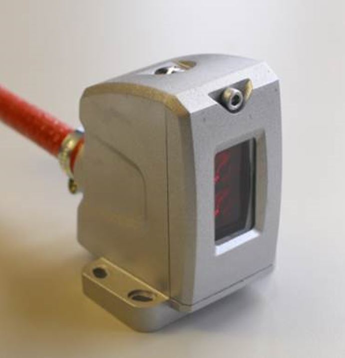
Photoelectric sensors with laser and red-light are widely used in all areas of industrial automation. A clean, dust-free and dry environment is usually essential for the proper operation of photoeyes, however, they can be the best choice in many dirty and harsh applications. Examples of this are raw steel production in steel mills and further metallurgical processes down to casting and hot-rolling.

Cutting of billets at casting – Photo: M.Münzl

Photoelectric sensors are especially useful in these environments thanks to their long sensing distance and their ability to detect objects independent of their material.

Most photoelectric sensors are approved to work in ambient temperatures of 55 to 60 °C. The maximum temperature range of these sensors is most often limited by the specifications of the optical components of the sensor, like the laser-diodes, but by taking certain precautions photoelectric sensors can provide optimal use in much hotter applications.

Maximize the distance
In steel production many parts of the process are accompanied by high ambient temperatures. Liquid steel and iron have temperatures from 1400 to 1536 °C. Material temperature during continuous casting and hot-rolling are lower but still between 650 and 1250°C.

The impact of heat emission on the sensors can be reduced significantly by placing the sensor as far from the target object as possible, something you can’t do with inductive sensors which have a short range. Very often the remote mounting will allow the sensor to operate at room temperature.

If you intend to detect quite small objects with high precision, the maximum distance for the installation might be limited. For this purpose chemical resistant glass fibers are suitable and can handle temperatures up to 250 °C. These pre-fabricated fiber optic assemblies can be easily attached to the sensor. The sensor itself can be mounted on a cooler and protected place.

Detect Glowing Metals
If you want to reliably detect red-hot or white glowing steel parts with temperatures beyond 700 °C, you won’t be able to use standard laser or red-light sensors. Red-hot steel emits light at the same wavelength that it is used by photoelectric sensors. This can interfere with the function of the sensor. In such applications you need to use sensors which operate based on infrared light.

Add Protection

Sensor enclosure and protective cable sleeve

At many locations in the steel production process, the extensive heat is only temporary. In a hot rolling mill, a slab runs through a rougher mill multiple times before it continues to a multi-stage finishing mill stand to be rolled to the final thickness. After that the metal strip runs into the coiler to be winded up.
This process runs in sequence, and the glowing material is only present at each stage of production for a short time. Until a new slab runs out of the reheating furnace, temperatures normalize.

Standard sensors can work in these conditions, but you do run the risk of even temporary temperature hikes causing sensor failure and then dreaded downtime. To protect photoelectric sensors against temporary overheating, you can use a protective enclosure. These can provide mechanical and thermal protection to the sensors which often have plastic bodies. Additional protection can be achieved when a heat resistant sleeve is used around the cable.

Photoelectric sensors do have their limits and are not suitable for all applications, even when precautions are taken. Ask yourself these questions when deciding if they can be the right solution for your high temperature applications.

  • Which distance between the hot object and sensor can be realized?
  • What is the maximum temperature at this location?
  • How long will the sensor be exposed to the highest heat levels during normal operation and at breakdown?

How to Select the Best Lighting Techniques for Your Machine Vision Application

Guest contributor,  Dan Simmons, Balluff

The key to deploying a robust machine vision application in a factory automation setting is ensuring that you create the necessary environment for a stable image.  The three areas you must focus on to ensure image stability are: lighting, lensing and material handling.  For this blog, I will focus on the seven main lighting techniques that are used in machine vision applications.

On-Axis Ring Lighting

On-axis ring lighting is the most common type of lighting because in many cases it is integrated on the camera and available as one part number. When using this type of lighting you almost always want to be a few degrees off perpendicular (Image 1A).  If you are perpendicular to the object you will get hot spots in the image (Image 1B), which is not desirable. When the camera with its ring light is tilted slightly off perpendicular you achieve the desired image (Image 1C).

Off-Axes Bright Field Lighting

Off-axes bright field lighting works by having a separate LED source mounted at about 15 degrees off perpendicular and having the camera mounted perpendicular to the surface (Image 2A). This lighting technique works best on mostly flat surfaces. The main surface or field will be bright, and the holes or indentations will be dark (Image 2B).

Dark Field Lighting

Dark field lighting is required to be very close to the part, usually within an inch. The mounting angle of the dark field LEDs needs to be at least 45 degrees or more to create the desired effect (Image 3A).  In short, it has the opposite effect of Bright Field lighting, meaning the surface or field is dark and the indentations or bumps will be much brighter (Image 3B).

Back Lighting

Back lighting works by having the camera pointed directly at the back light in a perpendicular mount.  The object you are inspecting is positioned in between the camera and the back light (Image 4A).  This lighting technique is the most robust that you can use because it creates a black target on a white background (Image 4B).

Diffused Dome Lighting

Diffused dome lighting, aka the salad bowl light, works by having a hole at the top of the salad bowl where the camera is mounted and the LEDs are mounted down at the rim of the salad bowl, pointing straight up which causes the light to reflect off of the curved surface of the salad bowl and it creates very uniform reflection (Image 5A).  Diffused dome lighting is used when the object you are inspecting is curved or non-uniform (Image 5B). After applying this lighting technique to an uneven surface or texture, hotspots and other sharp details are deemphasized, and it creates a sort of matte finish to the image (Image 5C).

Diffused On-Axis Lighting

Diffused on-axis lighting, or DOAL, works by having a LED light source pointed at a beam splitter and the reflected light is then parallel with the direction that the camera is mounted (Image 6A).  DOAL lighting should only be used on flat surfaces where you are trying to diminish very shiny parts of the surface to create a uniformed image.  Applications like DVD, CD, or silicon wafer inspection are some of the most common uses for this type of lighting.

6A
Image 6A


Structured Laser Line Lighting

Structured laser line lighting works by projecting a laser line onto a three-dimensional object (Image 7A), resulting in an image that gives you information on the height of the object.  Depending on the mounting angle of the camera and laser line transmitter, the resulting laser line shift will be larger or smaller as you change the angle of the devices (Image 7B).  When there is no object the laser line will be flat (Image 7C).

Real Life Applications 

The images below, (Image 8A) and (Image 8B) were used for an application that requires the pins of a connector to be counted. As you can see, the bright field lighting on the left does not produce a clear image but the dark field lighting on the right does.

This next example (Image 9A) and (Image 9B) was for an application that requires a bar code to be read through a cellophane wrapper.  The unclear image (Image 9A) was acquired by using an on-axis ring light, while the use of dome lighting (Image 9B) resulted in a clear, easy-to-read image of the bar code.

This example (Image 10A), (Image 10B) and (Image 10C) highlights different lighting techniques on the same object. In the (Image 10A) image, backlighting is being used to measure the smaller hole diameter.  In image (Image 10B) dome lighting is being used for inspecting the taper of the upper hole in reference to the lower hole.  In (Image 10C) dark field lighting is being used to do optical character recognition “OCR” on the object.  Each of these could be viewed as a positive or negative depending on what you are trying to accomplish.


cropped-cmafh-logo-with-tagline-caps.png

CMA/Flodyne/Hydradyne is an authorized  Balluff distributor in Illinois, Wisconsin, Iowa and Northern Indiana.

In addition to distribution, we design and fabricate complete engineered systems, including hydraulic power units, electrical control panels, pneumatic panels & aluminum framing. Our advanced components and system solutions are found in a wide variety of industrial applications such as wind energy, solar energy, process control and more.

Boost Connectivity with Non-Contact Couplings

Guest contributor, Shishir Rege, Balluff

In press shops or stamping plants, downtime can easily cost thousands of dollars in productivity. This is especially true in the progressive stamping process where the cost of downtime is a lot higher as the entire automated stamping line is brought to a halt.

BIC presse detail 231013

Many strides have been made in modern stamping plants over the years to improve productivity and reduce the downtime. This has been led by implementing lean philosophies and adding error proofing systems to the processes. In-die-sensing is a great example, where a few inductive or photo-eye sensors are added to the die or mold to ensure parts are seated well and that the right die is in the right place and in the right press. In-die sensing almost eliminated common mistakes that caused die or mold damages or press damages by stamping on multiple parts or wrong parts.

In almost all of these cases, when the die or mold is replaced, the operator must connect the on-board sensors, typically with a multi-pin Harting connector or something similar to have the quick-connect ability. Unfortunately, often when the die or mold is pulled out of the press, operators forget to disconnect the connector. The shear force excreted by the movement of removing the die rips off the connector housing. This leads to an unplanned downtime and could take roughly 3-5 hours to get back to running the system.

image

Another challenge with the multi-conductor connectors is that over-time, due to repeated changeouts, the pins in the connectors may break causing intermittent false trips or wrong die identification. This can lead to serious damages to the system.

Both challenges can be solved easily with the use of a non-contact coupling solution. The non-contact coupling, also known as an inductive coupling solution, is where one side of the connectors called “Base” and the other side called “Remote” exchange power and signals across an air-gap. The technology has been around for a long time and has been applied in the industrial automation space for more than a decade primarily in tool changing applications or indexing tables as a replacement for slip-rings. For more information on inductive coupling here are a few blogs (1) Inductive Coupling – Simple Concept for Complex Automation Part 1,  (2) Inductive Coupling – Simple Concept for Complex Automation Part 2

For press automation, the “Base” side can be affixed to the press and the “Remote” side can be mounted on a die or mold, in such a way that when the die is placed properly, the two sides of the coupler can be in the close proximity to each other (within 2-5mm). This solution can power the sensors in the die and can help transfer up to 12 signals. Or, with IO-Link based inductive coupling, more flexibility and smarts can be added to the die. We will discuss IO-Link based inductive coupling for press automation in an upcoming blog.

Some advantages of inductive coupling over the connectorized solution:

  • Since there are no pins or mechanical parts, inductive coupling is a practically maintenance-free solution
  • Additional LEDs on the couplers to indicate in-zone and power status help with quick troubleshooting, compared to figuring out which pins are bad or what is wrong with the sensors.
  • Inductive couplers are typically IP67 rated, so water ingress, dust, oil, or any other environmental factor does not affect the function of the couplers
  • Alignment of the couplers does not have to be perfect if the base and remote are in close proximity. If the press area experiences drastic changes in humidity or temperature, that would not affect the couplers.
  • There are multiple form factors to fit the need of the application.

In short, press automation can gain a productivity boost, by simply changing out the connectors to non-contact ones.


cropped-cmafh-logo-with-tagline-caps.png

CMA/Flodyne/Hydradyne is an authorized  Balluff distributor in Illinois, Wisconsin, Iowa and Northern Indiana.

In addition to distribution, we design and fabricate complete engineered systems, including hydraulic power units, electrical control panels, pneumatic panels & aluminum framing. Our advanced components and system solutions are found in a wide variety of industrial applications such as wind energy, solar energy, process control and more.

Improve Your Feeder Bowl System (and Other Standard Equipment) with IO-Link

Guest contributor: Tom Rosenberg, Balluff

One of the most common devices used in manufacturing is the tried and true feeder bowl system. Used for decades, feeder bowls take bulk parts, orient them correctly and then feed them to the next operation, usually a pick-and-place robot. It can be an effective device, but far too often, the feeder bowl can be a source of cycle-time slowdowns. Alerts are commonly used to signal when a feed problem is occurring but lack the exact cause of the slow down.

feeder bowl

A feed system’s feed rate can be reduced my many factors. Some of these include:

  • Operators slow to add parts to the bowl or hopper
  • Hopper slow to feed the bowl
  • Speeds set incorrectly on hopper, bowl or feed track
  • Part tolerance drift or feeder tooling out of adjustment

With today’s Smart IO-Link sensors incorporating counting and timing functions, most of the slow-down factors can be easily seen through an IIoT connection. Sensors can now time how long critical functions take. As the times drift from ideal, this information can be collected and communicated upstream.

A common example of a feed system slow-down is a slow hopper feed to the bowl. When using Smart IO-Link sensors, operators can see specifically that the hopper feed time is too long. The sensor indicates a problem with the hopper but not the bowl or feed tracks. Without IO-Link, operators would simply be told the overall feed system is slow and not see the real problem. This example is also true for the hopper in-feed (potential operator problem), feed track speed and overall performance. All critical operations are now visible and known to all.

For examples of Balluff’s smart IO-Link sensors, check out our ADCAP sensor.


cropped-cmafh-logo-with-tagline-caps.pngCMA/Flodyne/Hydradyne is an authorized  Balluff distributor in Illinois, Wisconsin, Iowa and Northern Indiana.

In addition to distribution, we design and fabricate complete engineered systems, including hydraulic power units, electrical control panels, pneumatic panels & aluminum framing. Our advanced components and system solutions are found in a wide variety of industrial applications such as wind energy, solar energy, process control and more.

Polarized Retroreflective Sensors: A Solution for Detecting Highly Reflective Objects

Guest contributor: Alejandro Romero, Balluff

The complexity of factory automation creates constant challenges which drive innovation in the industry. One of these challenges involves the ability to accurately detect the presence of shiny or highly reflective objects. This is a common challenge faced in a variety of applications, from sensing wheels in an automotive facility to detecting an aluminum can for filling purposes at a beverage plant. However, thanks to advancements in photoelectric sensing technologies, there is a reliable solution for those type of applications.

Why are highly reflective objects a challenge?

Light reflects from these types of objects in different directions, and with minimum energy loss. This can cause the receiver of a photoelectric sensor to be unable to differentiate between a signal received from the emitter or a signal received from a shiny object. In the case of a diffuse sensor, there is also the possibility that when trying to detect a shiny object, the light will reflect away from the receiver causing the sensor to ignore the target.

So how do we control the direction of the light going back to the receiver, and avoid false triggering from other light sources? The answer is in polarized retroreflective sensors.

Retroreflective sensors require a reflector which reflects the light back to the sensor allowing it to be captured by the receiver. This is achieved by incorporating sets of three mirrors oriented at right angles from each other (referred to as corner cubes). A light beam entering this system is reflected by all three surfaces and exits parallel to the incident beam. Additionally, corner cubes are said to be optically active as they rotate the plane of oscillation of the light by 90 degrees. This concept, along with polarization, allow this type of sensor to accurately detect shiny objects.

Polarization

Light emitted by a regular light source oscillates in planes on dispersal axes. If the light meets a polarizing filter (fine line grid), only the light oscillating parallel to the grid is let through (see figure 1 below).

Figure-1_AR
Figure 1
In polarized retroreflective sensors, a horizontal polarized filter is placed in front of the emitter and a vertical one in front of the receiver. By doing this, the transmitted light oscillates horizontally until it hits the reflector. The corner cubes of the reflector would then rotate the polarization direction by 90 degrees and reflect the light back to the sensor. This way, the returning light can pass through the vertical polarized filter on the receiver as shown below.

Figure-2_AR
Figure 2
With the use of polarization and corner cubed reflectors, retroreflective sensors can create a closed light circuit which ensures that light detected by the receiver was sourced exclusively by the emitter. This creates a great solution for applications where highly reflective targets are influencing the accuracy of sensors or causing them to malfunction. By ensuring proper operation of photoelectric sensors, unplanned downtime can be avoided, and overall process efficiency can be improved.

cropped-cmafh-logo-with-tagline-caps.pngCMA/Flodyne/Hydradyne is an authorized  Balluff distributor in Illinois, Wisconsin, Iowa and Northern Indiana.

In addition to distribution, we design and fabricate complete engineered systems, including hydraulic power units, electrical control panels, pneumatic panels & aluminum framing. Our advanced components and system solutions are found in a wide variety of industrial applications such as wind energy, solar energy, process control and more.

What to Ask Before You Build an RFID System to Meet Your Traceability Needs

Guest contributor, Balluff

overview_rfid

An industrial RFID system is a powerful solution for reliably and comprehensively documenting individual working steps in manufacturing environments. But an industrial RFID system that meets your application needs isn’t available off-the-shelf. To build the system you need, it is important to consider what problems you hope RFID will solve and what return on investments you hope to see.

RFID can deliver many benefits, including process visibility and providing data needed to better manage product quality. It can be used to improve safety, satisfaction and profit margins. It can even be used to help comply with regulatory standards or to manage product recalls. And RFID can be used in a wide range of applications from broad areas like supply management to inventory tracking to more specific applications. These improvements can improve time, cost or performance—though not typically all three.

It is essential to understand and document the goal and how improvements will be measured to in order to plan a RFID system (readers, antennas, tags, cables) to best meet those goals.

Other important questions to consider:

Will the system be centralized or de-centralized? Will the system be license plate only or contain process data on the tag?

How will the data on the tags be used?  Will the information be used to interface with a PLC, database or ERP? Will it be used to provide MES or logical functionality? Or to provide data to an HMI or web browser/cloud interface?

Will the system be required to comply with any international regulations or standards? If so, which ones: EPC Global, Class 1 Gen 2 (UHF only), ISO 15693, or 14443 (HF only)?

What environment does the system need to perform in? Will it be used indoor or outdoor? Will it be exposed to liquids (cleaning fluids, coolants, machine oils, caustics) or high or low temperatures?

Does the RFID system need to work with barcodes or any other human readable information?

What are the performance expectations for the components? What is the read/write range distance from head to tag? What is the station cycle timing? Is the tag metal-mounted? Does the tag need to be reused or be disposable? What communication bus is required?

With a clear set of objectives and goals, the mechanical and physical requirements discovered by answering the questions above, and guidance from an expert, a RFID system can be configured that meets your needs and delivers a strong return on investment.

cropped-cmafh-logo-with-tagline-caps.pngCMA/Flodyne/Hydradyne is an authorized  Balluff distributor in Illinois, Wisconsin, Iowa and Northern Indiana.

In addition to distribution, we design and fabricate complete engineered systems, including hydraulic power units, electrical control panels, pneumatic panels & aluminum framing. Our advanced components and system solutions are found in a wide variety of industrial applications such as wind energy, solar energy, process control and more.

When to Use Hygienic Design vs. Washdown

Guest Contributor: Christine Rühling, Balluff

Both washdown and hygienic design are common terms used in the food and beverage industry, and are increasingly being used in the packaging industry. These terms are used in different scenarios and easily confused with each other. What exactly are the differences between them, and in what applications are each used?

Why are hygienic design and washdown needed?

The consumer, and more specifically, the health of the consumer is the core concern of the food and beverage industry. Contaminated food can pose a danger to life and limb. A product recall damages the image of a company, costs a lot of money and as a worst case scenario can lead to the complete closing of the company. To prevent such scenarios, a producers primary objective is to make sure that the food is safe and risk-free for the consumer.image 1
In food manufacturing and packaging plants, a differentiation is made between the food area (in direct contact with the product), the spray area (product-related) and the non-food area. The requirements of the machine components are different depending on which area they are in.

The Food Area

In the food area the food is unpacked, or partially unpacked, and particularly susceptible to contamination. All components and parts that may come in contact with the food must not adversely affect this, e.g. in terms of taste and tolerability.
The following needs to be considered to avoid contamination:

  • Hygiene in production
  • Use of food contact materials
  • Food-grade equipment in Hygienic Design

These requirements result in the need for components that follow the hygienic design rules. If the component supplier fulfills these rules, the machine manufacturer can use the components and the producer can use the machines without hesitation.

Hygienic Design

Many component suppliers offer different solutions for hygienic design and each supplier interprets the design differently. So what does hygienic design mean? What must be included and which certifications are the right ones?

  • The material used must be FoodContact Material (FCM). This means that the material is non-corrosive, non-absorbent and non-contaminating, disinfectable, pasteurisable and sterilizable.
  • Seals must be present to prevent the ingress of microorganisms.
  • The risk of part loss must be minimized.
  • Smooth surfaces with a radius of < 0.8 μm are permitted.
  • There must be no defects, folds, breaks, cracks, crevices, injection-molded seams, or joints, even with material transitions.
  • There must be no holes or depressions and no corners of 90°.
  • The minimum radius should be 3 mm.

Supporting institutions and related certifications

There are different institutions which confirm and verify the fulfillment of these rules. They also support the companies during the development process.
image2
EHEDG – The European Hygienic Engineering and Design Group offers machine builders and component suppliers the possibility to evaluate and certify their products according to Hygienic Design requirements.
image33A – 3-A Sanitary Standards, Inc. (3-A SSI) is an independent, non-profit corporation in the U.S. for the purpose of improving hygiene design in the food, beverage and pharmaceutical industries. The 3-A guidelines are intended for the design, manufacture and cleaning of the daily food           accessories used in handling, manufacturing and packaging of edible products with high hygiene requirements.
image4FDA – The Food and Drug Administration is a federal agency of the United States Department of Health and Human Services, one of the United States federal executive departments. Among other things, the FDA is responsible for food safety.

What does a hygienic design product look like?

Below is an example of a hygienic design product.


  • Stainless steel housing VA 1.4404
  • Laser marking
  • Protection class IP69K (IEC 60529)
  • Active surface made of PEEK
  • EHEDG conform
  • FDA conform

Since the product contacting area is associated with high costs for the plant manufacturer and the operator, it’s beneficial to keep it as small as possible.

The Spray Area

In the spray area, there are different requirements than in the food area.
Depending on the type of food that is processed, a further distinction is made between dry and wet areas.

image6
Areas in the food and beverage production

Here we are talking about the washdown area. Washdown capable areas are designed for the special environmental conditions and the corresponding cleaning processes.

Washdown

Components which fulfill washdown requirements usually have the following features:

  • Cleaning agent/corrosion resistant materials (often even food compliant, but this is not a must)
  • High protection class (usually IP 67 and IP 69K)
  • Resistant to cleaning agents
image7
Photoelectric sensor for washdown requirements

Ecolab and Diversey are two well-known companies whose cleaning agents are used for appropriate tests:
Ecolab Inc. and Diversey Inc. are US based manufacturers of cleaning agents for the food and beverage industry. Both companies offer certification of equipment’s resistance to cleaning agents. These certificates are not prescribed by law and are frequently used in the segments as proof of stability.
The washdown component must also be easy and safe to clean. However, unlike the hygienic design, fixing holes, edges and threads are permitted here.

For basic information on IP69K see also this previous blog post.
To learn more about solutions for washdown and hygienic design click here.

cropped-cmafh-logo-with-tagline-caps.pngCMA/Flodyne/Hydradyne is an authorized  Balluff distributor in Illinois, Wisconsin, Iowa and Northern Indiana.

In addition to distribution, we design and fabricate complete engineered systems, including hydraulic power units, electrical control panels, pneumatic panels & aluminum framing. Our advanced components and system solutions are found in a wide variety of industrial applications such as wind energy, solar energy, process control and more.


Improving sawmill yield through automation

Guest contributor: Christian Holder, Balluff

It is not a surprise that optimizing yield is one of the most important objectives in a sawmill (or lumber mill) as it is in any other industry. The big difference is that there is hardly any control over the quality of the logs that enter the sawill. In the ideal world all logs are not only cylindrical in shape but also straight. But obviously each individual log is unique in shape. Crooked, out-of-round, or tapered logs are common and even worse: usually it is a combination of these shapes.

Still the target is to recover as much yield from each log as possible. Therefore sawmills turn into highly automated factories with three dimensional (3D) measurement of logs, and advanced equipment for primary and secondary breakdown. Basically there are three areas of automation in a sawmill:

  1. 3D measurement for optimum cutting pattern to recover most yield from a log
  2. Automation of drives to position the log itself, or tools (e.g. sawblades, knifes, canter heads…) at high velocity to increase throughput
  3. Automation of log and lumber handling to minimize the gap between the logs

All of the three areas support the sawmill’s target to get the most out of the logs at the highest speed. The worst case is any downtime as it directly impacts the whole log to lumber process. Therefore electrical engineers look for sensors that meet the challenges of the sawmill environment. Mainly sensors must meet high vibration and shock standards. As they are exposed to the environment, protective housings help to protect the sensors from logs crashing into them.

From logs to lumber

Wave feeder with analog distance sensor

To efficiently process logs to lumber, sawmills use dedicated equipment for different sizes of logs. As a result bigger mills have a primary and a secondary breakdown area. Independent from the logs, sawmills aim to minimize the gaps and to avoid changes in the setup. This allows them to run faster and to increase the production rate. Here is the process how a log turns into lumber in a sawmill.

When a log arrives at the mill it is indexed onto the infeed conveyer (could be a step feeder or log loader). Either inductive sensors sequence the steps. Or a magnetostrictive position sensor (linear transducer) provides feedback of the step position of the loader to control motion and speed. Once the log is on the loader analog distance sensors determine the distance to the end of the log from the side of the loader wall.

This is to ensure a constant distance between the logs (log gap) as they enter the sawmill. Knowing the distance enables them to control when the log is loaded on the conveyor. And thereby they can control the gap. As an alternative photoelectric a thru beam sensor determines if a log is present for the final two steps on a loader. These sensors work with a long measuring range. Additionally they have a large functional reserve and are very resistant to dirt and dust.

Primary breakdown – from raw log to slabs and cants

The first step of the log is to run through a debarker that removes the bark. As there are tolerances in shape, linear transducers and photoelectric analog distance sensors are used to determine log sizes. These sizes help to adjust the debarker’s pressure and speed. After debarking the logs are cut to the best pre-determined length by cut-off or bucking saws. Again linear transducers are used to control the motion of the cut-off saw swing.

By stacking some photoelectric through beam sensors they can be used to determine the log diameter roughly. This leads to increasing speed as the saw can cut through smaller logs faster and has to slow down for larger logs. Many mills just sort their debarked logs into “large logs” and “small logs” based on their diameters.  And then go into machines that are set up for those particular log sizes.

Log carriage for 20″ (50cm) logs and more

Carriage saw using BTL for clamping and positioning
Carriage saw with BTL for positioning

Many mills also run a lot of larger logs and therefore have a log carriage. This is a single band saw with a carriage that runs on railway style tracks. The carriage has three or four knees that have positioners and log clamps (dogs) that hold the log. In the knees hydraulic cylinders with magnetostrictive transducers position the log. Even under extreme surrounding conditions, these position sensors guarantee a high machine and system availability. The clamps hold the log while it movesthrough the band saw. The carriage cuts the logs into slabs (two flat, two rounded sides) or into cants (four flat, square sides).

Secondary Breakdown – from small logs, slabs and cants to lumber

Mills that run smaller logs do not have to break down the logs prior to putting them through the secondary breakdown equipment. After the cut-off saw, the small logs will be sorted by size into bins. Step feeders index them again onto a conveyor and that feeds them through a Scanner into the small log line machine. To recover as much yield as possible log turners turn the logs in the optimum position. Chipper canters center them to enable curve sawing, which leads to increased lumber recovery.

Hydraulic drives dominate small log lines and all motion control happens with linear position transducers. Typical small log lines consist of log turning and centering, chipping with canter heads, saw box slew and skew, saw box positioniers, profiling heads and outfeed pickers. All of the equipments’ design aims for speed and therefore they require fast and accurate position feedback. Sensors and transducers must withstand high shock and vibration. Balluff’s products survive even in toughtest environments and undergo intensive shock and vibration testing.

Shifting edgers and curve sawing

Edgers using BTL for curve sawing
Sawblade Adjustment with BTL

Gang edgers and shifting edgers cut cants and slabs from the primary breakdown into boards. Gang edgers have circular saws stacked at fixed spacing. Shifting edgers look similar to gang edgers except that they change spacing  between saw blades can be changed. Therefore each saw is connected to a hydraulic positioner. A scanner looks at the cant or slab and determines the best solutions of cuts to produce best results. After the scanner the positioners of the shifting edgers set the new saw spacing to match that solution.

Edger optimizers pre-position the board and optimize the infeed to get the best payback from the machine. Photoelectric (laser) retroreflective sensors  track boards through the ducker table. The infeed position cylinder (with integrated linear transducer) skews the board in the best position to be fed in the edger.

Trimming, sorting, stacking, strapping, shipping

Photoelectric sensors detect boards at the trimmer infeed

The boards go into bins when they come out of the edgers. Another scanner determines if the board can be cut down into shorter boards. Or if a damaged end needs to be cut off so that the board is not graded lower. The next step is processing the board through a trimmer. The trimmer is a set of up to about a dozen circular saws positioned across the conveyor. It can cut longer boards down into two or three shorter boards or just trim the ends.

Photoelectric analog distance sensors detect stacked boards from high distance

Background suppression photoelectric sensors at the indeed of the trimmer look down at the board as it goes into the machine. And they determine if the board is actually as long as the scanner information indicates. The same sensors confirm after the trimmer that the board was cut down to the proper size. After the trimmer they go into a sorter and and from there to stacking and strapping to final shipment.

We provide additional information how our sensors help to automate sawmills on our website.

Veneer instead of solid wood

A sawmill produces solid wood. This means that the board is out of one piece of wood. Another type of boards is veneer. This means that thin layers of wood are glued together to reach a board. Usually these layers are less that 3 mm thick. A lathe continuously turns a log against a blade to peel it. With each rotation the log becomes thinner. Therefore the blade position needs to be adjusted. Hydraulic cylinders with integrated linear transducers centerthe log and position the blade to peel the trunk. The thin layers are glued together in a veneer press.

Not only stationary, but also portable sawmills

In the end our sensors and transducers not only help to automate huge mills, but also portable sawmills. Magnetostrictive or magnetically sensors enable operators to exactly position the saw unit. So they achieve accurate and fast cutting of boards. Wood-Mizer is a world leading supplier of efficient and fast portable sawmills that uses magnetostrive position sensors in it’s machines. The reasons for Balluff are its product and service quality as well as the availability.

cropped-cmafh-logo-with-tagline-caps.png

CMA/Flodyne/Hydradyne is an authorized  Balluff distributor in Illinois, Wisconsin, Iowa and Northern Indiana.

In addition to distribution, we design and fabricate complete engineered systems, including hydraulic power units, electrical control panels, pneumatic panels & aluminum framing. Our advanced components and system solutions are found in a wide variety of industrial applications such as wind energy, solar energy, process control and more.