Guest Contributor: Christine Rühling, Balluff
Both washdown and hygienic design are common terms used in the food and beverage industry, and are increasingly being used in the packaging industry. These terms are used in different scenarios and easily confused with each other. What exactly are the differences between them, and in what applications are each used?
Why are hygienic design and washdown needed?
The consumer, and more specifically, the health of the consumer is the core concern of the food and beverage industry. Contaminated food can pose a danger to life and limb. A product recall damages the image of a company, costs a lot of money and as a worst case scenario can lead to the complete closing of the company. To prevent such scenarios, a producers primary objective is to make sure that the food is safe and risk-free for the consumer.
In food manufacturing and packaging plants, a differentiation is made between the food area (in direct contact with the product), the spray area (product-related) and the non-food area. The requirements of the machine components are different depending on which area they are in.
The Food Area
In the food area the food is unpacked, or partially unpacked, and particularly susceptible to contamination. All components and parts that may come in contact with the food must not adversely affect this, e.g. in terms of taste and tolerability.
The following needs to be considered to avoid contamination:
- Hygiene in production
- Use of food contact materials
- Food-grade equipment in Hygienic Design
These requirements result in the need for components that follow the hygienic design rules. If the component supplier fulfills these rules, the machine manufacturer can use the components and the producer can use the machines without hesitation.
Hygienic Design
Many component suppliers offer different solutions for hygienic design and each supplier interprets the design differently. So what does hygienic design mean? What must be included and which certifications are the right ones?
- The material used must be FoodContact Material (FCM). This means that the material is non-corrosive, non-absorbent and non-contaminating, disinfectable, pasteurisable and sterilizable.
- Seals must be present to prevent the ingress of microorganisms.
- The risk of part loss must be minimized.
- Smooth surfaces with a radius of < 0.8 μm are permitted.
- There must be no defects, folds, breaks, cracks, crevices, injection-molded seams, or joints, even with material transitions.
- There must be no holes or depressions and no corners of 90°.
- The minimum radius should be 3 mm.
Supporting institutions and related certifications
There are different institutions which confirm and verify the fulfillment of these rules. They also support the companies during the development process.

EHEDG – The European Hygienic Engineering and Design Group offers machine builders and component suppliers the possibility to evaluate and certify their products according to Hygienic Design requirements.
 3A – 3-A Sanitary Standards, Inc. (3-A SSI) is an independent, non-profit corporation in the U.S. for the purpose of improving hygiene design in the food, beverage and pharmaceutical industries. The 3-A guidelines are intended for the design, manufacture and cleaning of the daily food accessories used in handling, manufacturing and packaging of edible products with high hygiene requirements.
![]() FDA – The Food and Drug Administration is a federal agency of the United States Department of Health and Human Services, one of the United States federal executive departments. Among other things, the FDA is responsible for food safety.
FDA – The Food and Drug Administration is a federal agency of the United States Department of Health and Human Services, one of the United States federal executive departments. Among other things, the FDA is responsible for food safety.
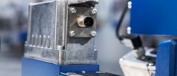
What does a hygienic design product look like?
Below is an example of a hygienic design product.


- Stainless steel housing VA 1.4404
- Laser marking
- Protection class IP69K (IEC 60529)
- Active surface made of PEEK
- EHEDG conform
- FDA conform
Since the product contacting area is associated with high costs for the plant manufacturer and the operator, it’s beneficial to keep it as small as possible.
The Spray Area
In the spray area, there are different requirements than in the food area.
Depending on the type of food that is processed, a further distinction is made between dry and wet areas.

Here we are talking about the washdown area. Washdown capable areas are designed for the special environmental conditions and the corresponding cleaning processes.
Washdown
Components which fulfill washdown requirements usually have the following features:
- Cleaning agent/corrosion resistant materials (often even food compliant, but this is not a must)
- High protection class (usually IP 67 and IP 69K)
- Resistant to cleaning agents

Ecolab and Diversey are two well-known companies whose cleaning agents are used for appropriate tests:
Ecolab Inc. and Diversey Inc. are US based manufacturers of cleaning agents for the food and beverage industry. Both companies offer certification of equipment’s resistance to cleaning agents. These certificates are not prescribed by law and are frequently used in the segments as proof of stability.
The washdown component must also be easy and safe to clean. However, unlike the hygienic design, fixing holes, edges and threads are permitted here.
For basic information on IP69K see also this previous blog post.
To learn more about solutions for washdown and hygienic design click here.
![]() CMA/Flodyne/Hydradyne is an authorized Balluff distributor in Illinois, Wisconsin, Iowa and Northern Indiana.
CMA/Flodyne/Hydradyne is an authorized Balluff distributor in Illinois, Wisconsin, Iowa and Northern Indiana.
In addition to distribution, we design and fabricate complete engineered systems, including hydraulic power units, electrical control panels, pneumatic panels & aluminum framing. Our advanced components and system solutions are found in a wide variety of industrial applications such as wind energy, solar energy, process control and more.


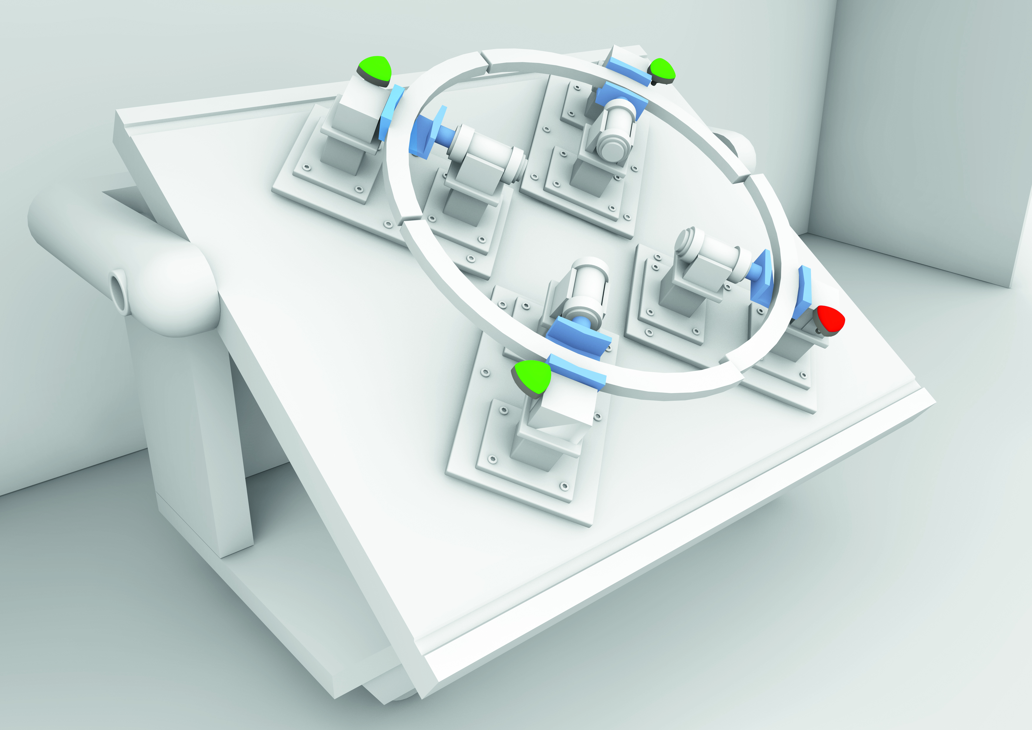 A manually-fed weld-cell with smart indicators is capable of not only signaling that the part is loaded correctly, but also if the part is out of alignment (shown by the red indicator) or that there is something wrong with one of the automation components such as a stuck pneumatic clamp.
 A traditional kitting station, sometimes referred to as a supermarket, with smart indicators to guide operators to the intended part to pull.
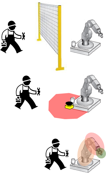 The typical machine/robot guarding scheme of the past used fences or hard guards to separate the human from the machine. Doors were controlled with safety interlock switches, which required the machine to stop on access, such as to load/unload parts or to perform maintenance or service, and this reduced productivity. It was also not 100% effective because workers inside a machine area or work cell might not be detected if another worker restarted the stopped machine. Other drawbacks included the cost of space, guarding, installation, and difficultly changing the work cell layout once hard guarding had been installed.


 builders and discrete manufacturers. For machine builders, the biggest advantage comes from the simplified wiring scheme of IO-Link devices. We have seen machine builder users of IO-Link reduce their wiring hardware & labor costs by 30%-60% for sensors,