Guest contributor: Eaton
Motors often require large amounts of energy when quickly accelerating to full speed. Soft starters and variable frequency drives can both be used to reduce inrush currents and limit torque— protecting your valuable equipment and extending the life of your motor by reducing motor heating caused by frequent starts and stops. Choosing between a soft starter and a variable frequency drive often depends on the application, system requirements, and cost (both for initial startup and over the life cycle of the system).
Soft starters
A soft starter is a solid-state device that protects AC electric motors from damage caused by sudden influxes of power by limiting the large initial inrush of current associated with motor startup. They provide a gentle ramp up to full speed and are used only at startup (and stop, if equipped). Ramping up the initial voltage to the motor produces this gradual start. Soft starters are also known as reduced voltage soft starters (RVSS).
Applications
Soft starters are used in applications where:
• Speed and torque control are required only during startup (and stop if equipped with soft stop)
• Reducing large startup inrush currents associated with a large motor is required
• The mechanical system requires a gentle start to relieve torque spikes and tension associated with normal startup (for example, conveyors, belt-driven systems, gears, and so on)
• Pumps are used to eliminate pressure surges caused in piping systems when fluid changes direction rapidly
How does a soft starter work?
Electrical soft starters temporarily reduce voltage or current input by reducing torque. Some soft starters may use solid-state devices to help control the flow of the current. They can control one to three phases, with three-phase control usually producing better results.

Most soft starters use a series of thyristors or silicon controlled rectifiers (SCRs) to reduce the voltage. In the normal OFF state, the SCRs restrict current, but in the normal ON state, the SCRs allow current. The SCRs are engaged during ramp up, and bypass contactors are pulled in after maximum speed is achieved. This helps to significantly reduce motor heating.
Benefits of choosing a soft starter
Soft starters are often the more economical choice for applications that require speed and torque control only during motor startup. Additionally, they are often the ideal solution for applications where space is a concern, as they usually take up less space than variable frequency drives.
Variable frequency drives
A variable frequency drive (VFD) is a motor control device that protects and controls the speed of an AC induction motor. A VFD can control the speed of the motor during the start and stop cycle, as well as throughout the run cycle. VFDs are also referred to as adjustable frequency drives (AFDs).
Applications
VFDs are used in applications where:
• Complete speed control is required
• Energy savings is a goal
• Custom control is needed
How do VFDs work?
VFDs convert input power to adjustable frequency and voltage source for controlling speed of AC induction motors. The frequency of the power applied to an AC motor determines the motor speed, based on the following equation:
N = 120 x f x p
N = speed (rpm)
f = frequency (Hz)
p = number of motor poles
For example, a four-pole motor is operating at 60 Hz. These values can be inserted into the formula to calculate the speed:
N = 120 x 60 x 4
N = 1800 (rpm)
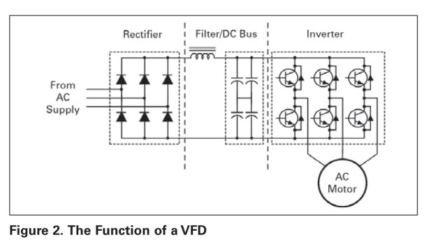
• AC supply: Comes from the facility power network (typically 480V, 60 Hz AC)
• Rectifier: Converts network AC power to DC power
• Filter and DC bus: Work together to smooth the rectified DC power and to provide clean, low ripple DC power to the inverter
• Inverter: Uses DC power from the DC bus and filter to invert an output that resembles sine wave AC power using a pulse width modulation (PWM) technique
• Pulse width modulation: Switches the inverter semiconductors in varying widths and times that, when averaged, create a sine waveform

Benefits of using a VFD
• Energy savings
• Reduces peak energy demand
• Reduces power when not required
• Fully adjustable speed (pumps, conveyors, and fans)
• Controlled starting, stopping, and acceleration
• Dynamic torque control
• Provides smooth motion for applications such as elevators and escalators
• Maintains speed of equipment, making drives ideal for manufacturing equipment and industrial equipment such as mixers, grinders, and crushers
• Versatility
• Self-diagnostics and communications
• Advanced overload protection
• PLC-like functionality and software programming
• Digital inputs/outputs (DI/DO)
• Analog inputs/outputs (AI/AO)
• Relay outputs
Energy savings
VFDs offer the greatest energy savings for fans and pumps. The adjustable flow method changes the flow curve and drastically reduces power requirements. Centrifugal equipment (fans, pumps, and compressors) follow a general set of speed affinity laws. The affinity laws define the relationship between speed and a set of variables:
• Flow
• Pressure
• Power
Based on the affinity laws, flow changes linearly with speed while pressure is proportional to the square of speed. The power required is proportional to the cube of the speed. The latter is most important, because if the motor speed drops, the power drops by the cube.

In this example, the motor is operated at 80 percent of the rated speed. This value can be inserted into the affinity laws formula to calculate the power at this new speed:

Therefore, the power required to operate the fan at 80 percent speed is half the rated power.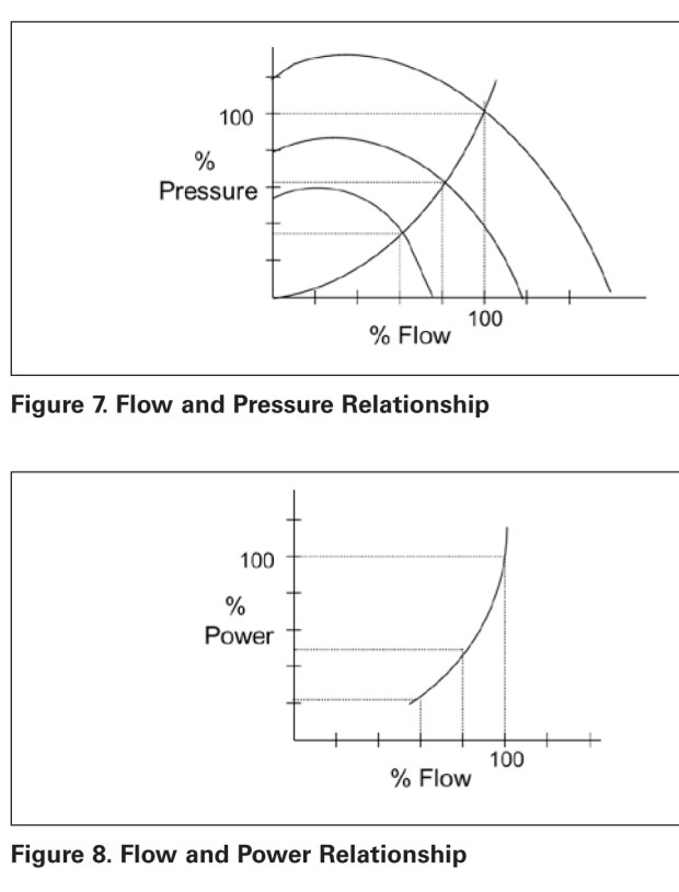
Selecting the correct equipment for your needs
Choosing a soft starter or a variable frequency drive often depends on your application. Soft starters are smaller and less expensive when compared with VFDs in larger horsepower applications. Larger VFDs take up more space and are usually more expensive than soft starters.
That being said, while a VFD is often more expensive up front, it can provide energy savings of up to 50 percent, thereby producing more cost savings over the life of the equipment.
Speed control is another advantage of a VFD, because it offers consistent acceleration time throughout the entire operating cycle of the motor, not just during startup. VFDs can also provide more robust functionality than soft starters offer, including digital diagnostic information.
It is important to note that a VFD can initially cost two to three times more than a soft starter. Therefore, if constant acceleration and torque control is not necessary, and your application requires current limiting only during startup, a soft starter may be a better solution from a cost standpoint.

CMA/Flodyne/Hydradyne is an authorized Eaton Electrical distributor in Illinois, Wisconsin, Iowa and Northern Indiana.
In addition to distribution, we design and fabricate complete engineered systems, including hydraulic power units, electrical control panels, pneumatic panels & aluminum framing. Our advanced components and system solutions are found in a wide variety of industrial applications such as wind energy, solar energy, process control and more.