Guest contributor: Jack Moermond, Balluff
Photoelectric sensors have been around for a long time and have made huge advancements in technology since the 1970’s. We have gone from incandescent bulbs to modulated LED’s in red light, infrared and laser outputs. Today we have multiple sensing modes like through-beam, diffuse, background suppression, retroreflective, luminescence, distance measuring and the list goes on and on. The outputs of the sensors have made leaps from relays to PNP, NPN, PNP/NPN, analog, push/pull, triac, to having timers and counters and now they can communicate on networks.
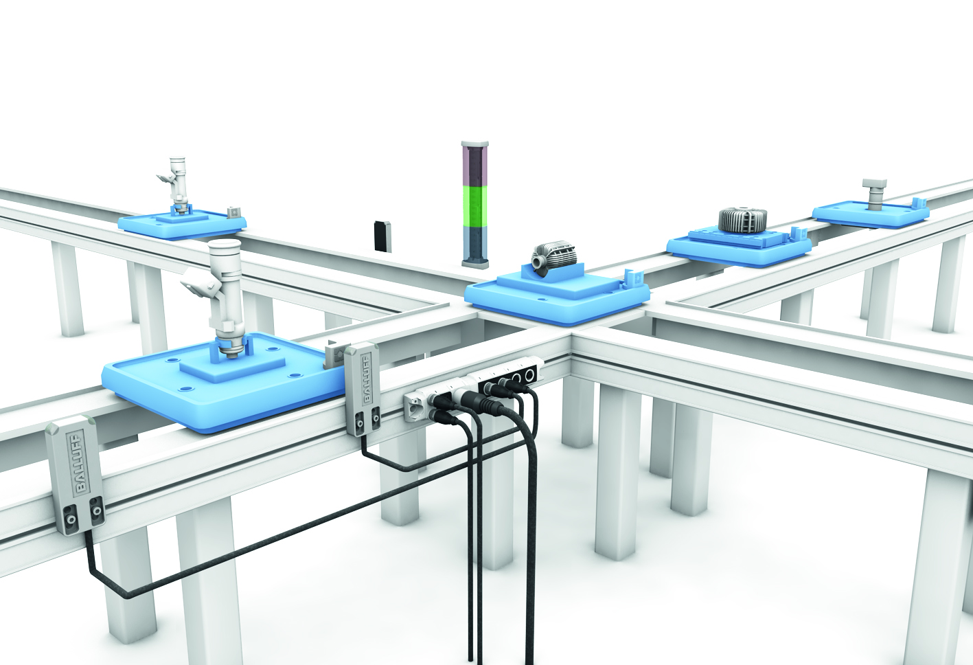
The ability of the sensor to communicate on a network such as IO-Link is now enabling sensors to be smarter and provide more and more information. The information provided can tell us the health of the sensor, for example, whether it needs re-alignment to provide us better diagnostics information to make troubleshooting faster thus reducing downtimes. In addition, we can now distribute I/O over longer distances and configure just the right amount of IO in the required space on the machine reducing installation time.
IO-Link networks enable quick error free replacement of sensors that have failed or have been damaged. If a sensor fails, the network has the ability to download the operating parameters to the sensor without the need of a programming device.
With all of these advancements in sensor technology why do we still have different sensors for each sensing mode? Why can’t we have one sensor with one part number that would be completely configurable?

Just think of the possibilities of a single part number that could be configured for any of the basic sensing modes of through-beam, retroreflective, background suppression and diffuse. To be able to go from 30 or more part numbers to one part would save OEM’s end users a tremendous amount of money in spares. To be able to change the sensing mode on the fly and download the required parameters for a changing process or format change. Even the ability to teach the sensing switch points on the fly, change the hysteresis, have variable counter and time delays. Just imagine the ability to get more advanced diagnostics like stress level (I would like that myself), lifetime, operating hours, LED power and so much more.
Obviously we could not have one sensor part number with all of the different light sources but to have a sensor with a light source that could be completely configurable would be phenomenal. Just think of the applications. Just think outside the box. Just imagine the possibilities. Let us know what your thoughts are.
To learn more about photoelectric sensors, visit www.balluff.com.
![]() CMA/Flodyne/Hydradyne is an authorized Balluff distributor in Illinois, Wisconsin, Iowa and Northern Indiana.
CMA/Flodyne/Hydradyne is an authorized Balluff distributor in Illinois, Wisconsin, Iowa and Northern Indiana.
In addition to distribution, we design and fabricate complete engineered systems, including hydraulic power units, electrical control panels, pneumatic panels & aluminum framing. Our advanced components and system solutions are found in a wide variety of industrial applications such as wind energy, solar energy, process control and more.


 extending the full length of the mechanical stroke. A magnet ring is used as a position marker and mounted on the face of the piston. As the piston (and the position marker) move, the linear position sensor provides a continuous absolute position by way of an analog or digital signal.
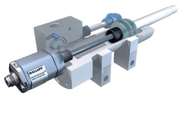


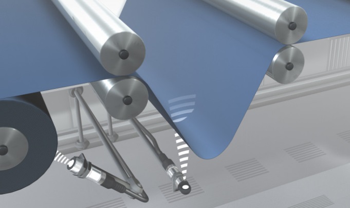 offerings as a go-to as they seem more common. Photoelectric sensors are solid performers, however they can run into limitations in certain applications. In these circumstances, considering an ultrasonic sensor could provide a solid solution.
 customer needed to detect a few features on a metal angle iron. The customer was currently using a laser photoelectric sensor with analog feedback measurement, however the results were not consistent or repeatable as the laser would simply pick up every imperfection that was present on the angle iron. This is where the ultrasonic sensors came in as they provide a larger detection range matched with emitting and receiving sound energy. This provided much more stable outputs, allowing the customer to reliably detect and error proof the angle iron. With the customer switching to ultrasonic sensors in this particular application they now have better quality control and less downtime.
 to think of all sensor technologies as some will provide better results than others. Ultrasonic sensors are indeed an excellent choice when applied correctly. They can measure fill levels, heights, sag, or simply monitor the presence of a target or object. They perform very well in foggy or dusty areas where some other sensor technologies fall short.